FX-20
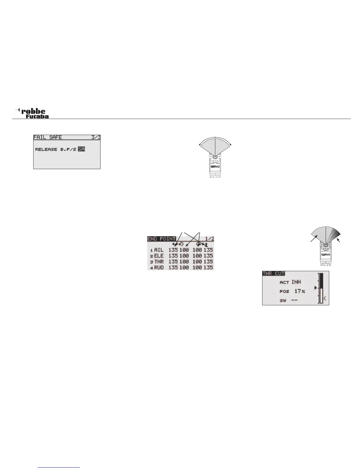
set up display. In the sample screen shown, switch SA is being
used as the release switch.
Important Note:
When checking that the Failsafe-settings are set correctly
on the throttle channel, remove the propeller or rotor
blades from the model to minimize the risk of personal
injury if the motor starts without warning. The settings can
also be checked by connecting a separate servo into the
throttle channel and testing the setting this way.
Once this has been done, you can test the Failsafe by swit-
ching off the transmitter.
Note:
The factory pre-set position for all channels is program-
med to HOLD. Check if this suits your model application.
10.10 SERVO THROW ADJUSTMENT (END POINT)
This function allows the servo
throws for all 8 channels to be set
each side of the neutral position.
This is necessary to stop the servo
hitting any mechanical limits impo-
sed by the linkages and controls.
For special cases, the servo throw
can be increased. This function
works on all servo channels and
any mixers active on the channel.
This menu allows you set each
channel with a servo throw limit at each end of the travel.
Please note that the changes also proportionally affect the trim
throw and any Dual-Rate settings that may have been set.
Using the “CAP TOUCH SENSOR“, highlight the ‘Limit’-Option
in Endpoint-Menu and select choice with “RTN”. The Set-up
display will be as follows:
Limit servo throw I + r
Servo throw settings
Highlight the right or left throw indicator of the channel you
would like to adjust with the “CAP TOUCH SENSOR“. The item
will now have a dark background. Set the servo throw by scrol-
ling the “CAP TOUCH SENSOR“ until the %-age value to suit
the control limit is reached. If the throw is also to be set for the
other direction of the servo travel, then repeat the process for
the second column of the channel.
The factory pre-set throw is 100%, the throw may be adjusted
between 30 ad 140%. Pressing the ‘RTN’-key for at least 1
second will reset it to the factory default.
Limit-Point Adjustment
The setting of the limit points follows the same procedure.
Highlight the required field and adjust using the “CAP TOUCH
SENSOR“. The limit point may be set for each servo travel
direction. The factory pre-set is 135%; the adjustment range is
between 0 and 155%. Pressing the ‘RTN’-key for a minimum of
1 second will revert back to the initial pre-set value.
Why use Limit-Endpoint Adjustment?
Due to a too high control input throw or the mixing of 2 functions
lead to the default servo travel being exceeded. To avoid me-
chanical damage to the servo hitting it’s end stop, one should
define the maximum servo throw as well as the linkage throw
using the Limit Point function. Therefore it stops the servo ex-
ceeding its mechanical travel Limit Point, immaterial of control
inputs and mixers settings are working on that servo.
10.11 THROTTLE CUT FUNCTION
This allows you to cut the motor with a switch without having to
touch the idle trim. It is a conve-
nient method to safely shut the
motor down.
Select the THR CUT menu in the
Linkage Menu using the “CAP
TOUCH SENSOR“ and access
by pressing “RTN”. The follow-
ing display will appear:
Activate the function by highlighting the ACT/INH line. Using
the “CAP TOUCH SENSOR“ change the setting from ‘INH’
to ‘ACT’ or ‘ON’, depending on the position of the throttle cut
switch and press ‘RTN’-Key. Now select a switch, with which
to cut the motor. Also highlight ‘--’ and open the switch setting
menu by pressing ‘RTN’-key. Choose a suitable switch and
ON position.
31
Linkage Menu
30-140%
left
30-140%
right
servo
throw
t h r o t t l e
off
throw