FX-20
13.3 THR CURVE/ HOVERING THROTTLE TRIM
Moving the Throttle/Pitch stick, not only moves the throttle
servo, but also the pitch servo will be controlled. To make inde-
pendent adjustments to match both curves, the throttle function
has a curve, with up to 5 programmable points available, which
can be coupled to the pitch curve.
Highlight “THR CURVE” with the “CAP TOUCH SENSOR“ in
the Helicopter Model-Menu and confirm with “RTN”.The Dis-
play has three pages/sub menus, which are as follows:
This Menu adjusts the Throttle Curves for the following Flight
Conditions:
• Normal: For starting and stopping the motor
• IDLE UP 1: For hovering flight
• IDLE UP 2: For circuit flying
• IDLE UP 3: For aerobatics
• HOLD: For autorotation landings
Switching between these flight conditions is made using the as-
signed (CONDITION) switches. When turning on the Transmit-
ter, the NORMAL flight condition must be selected, otherwise a
WARNING alarm will sound and you will be questioned whether
to transmit a signal…The YES or NO must be selected and
confirmed with RTN!
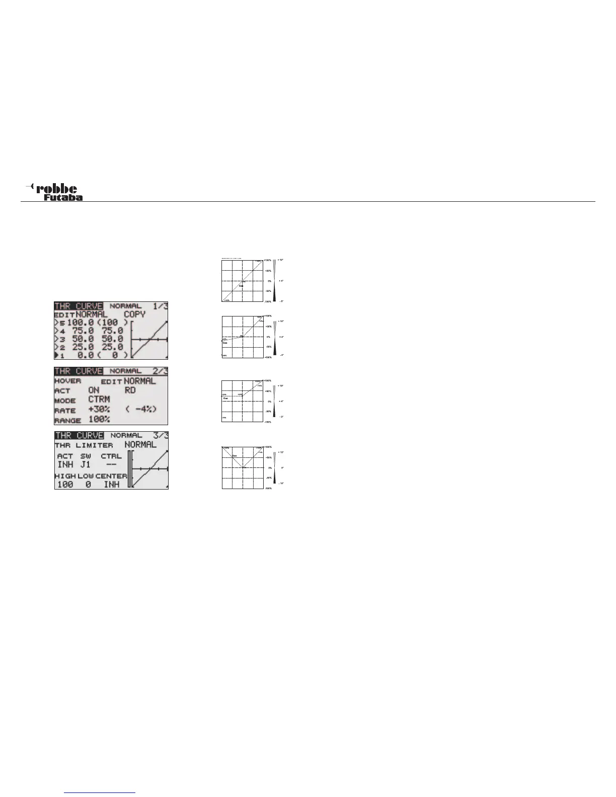
Example of the Pitch Curve for
‘NORMAL’ flight condition. Program
the curve so that the motor r.p.m.
remains as constant as possible
across the entire pitch range.
Example of a Curve for ‘IDLE UP 1’.
For hovering, the settings are adju-
sted so that the correct rpm is held
for all pitch settings.
Example of a Curve for “IDLE UP2”.
For circuit flying, the settings are ad-
justed so that the correct rpm is held
for all pitch settings.
Example of a Curve for “IDLE UP3”.
For 3D aerobatic flying, the basic
curve is a straight line. For 3D/in-
verted flying, a V-Curve is created
such that full throttle is commanded
at maximum negative as well as po-
sitive pitch settings. The aim is to
achieve constant rotor speed being
held for all upright and inverted pitch
settings.
The illustrated curves are only shown as examples, since
you must test fly your machine and adjust the individual
settings to suit the specific model characteristics!
The programming of the Throttle Curve for all flight conditions
is made in exactly the same way as for the Pitch Curve. The
same also applies for programming the Hovering Gas Trim, in
IDLE UP1 on page two of the menu.
Also it is possible to set up a different Throttle Curve of any
particular throttle flight condition without operating the Condi-
tion switches. This is useful for adjusting the IDLE UP 1,2 & 3
throttle curves on the ground with the motor running. In the
“EDIT“ line of the Display, select the required flight condition
throttle curve to be adjusted and press RTN and adjust as re-
quired.
To copy the modified curve to another Flight Condition, scroll
to and select “COPY” and select the destination Flight Condi-
tion to be replaced with the displayed pre-set curve. Following
a confirmation message (YES or NO), the existing condition
curve will be over-written with the new one.
THROTTLE LIMITER (3/3)
The Throttle Limiter can be used to set a point on the throttle
function so that it will be held to a limited opening whilst car-
rying it or programming is being carried out
Use MAX and Min to set the end point . Use CENTER to set
the middle of the 3 point curve and a Tx control, e.g. a linear
slide may used. Thereby one has a second throttle curve that
will allow the motor to run throttles back.
The Gas Limiter Position is programmed by using a separate
Tx control e,g. Linear Slider. The throttle servo remains at its
programmed position, even if the throttle stick is moved. The
Collective Pitch function remains fully controllable. Take heed
of the COMBination and SEPA Rate trim settings for the flight
condition.
Model menu helicopter
55