FX-20
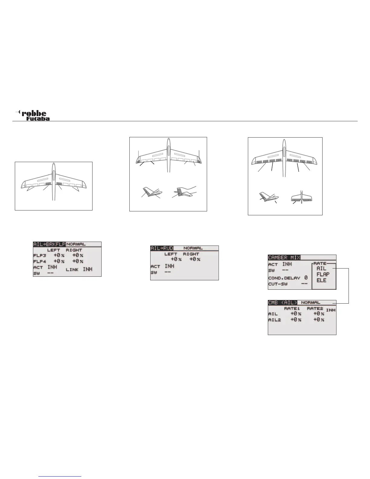
11.9 AIL->BRKFLP/ AILERON -> BRAKE FLAP MIXER
This mix operates the brake flaps (FLP3 /4) in aileron mode.
When the aileron is operated, the aileron and brake flaps ope-
rate as ailerons together to improve the axial roll response of
the model.
A d j u s t a b l e
mix rates
allow precise
flap throws to
be set. The
mix can be
turned ON/OFF during flight by selecting a mix switch and the
mix Linked with other mixers.
Using the “CAP TOUCH SENSOR“, select the AIL->BRAKEFLP
mix from Model Menu and confirm with RTN. The Display will
be:
Activate this mixer, scroll to ‘ACT/INH’, both flap throws may
be adjusted individually and set for left and right with the mix
rate for each defined as a % age value. + & - signs indicate
direction.
“SW” defines the switch selected and its direction of operation.
If it is required to link this mixer with AIL -> CMBFLP or RUD ->
AIL mixers, then the ‘LINK’ must be switched ON.
Similarly, the mixer required to be linked to must have the func-
tion enabled (ACT) and the „LINK“ enabled also. Note that the
Linked Mixer may not have a second control or switch assigned
to it, otherwise the “LINK“ Function will not work.
11.10 AILERON -> RUDDER MIXER
Activating this mixer will couple the Ailerons to the Rudder
functions. This is particularly useful in large models to avoid ad-
verse yaw effects occurring when banking to turn. The mix-rate
can be precisely set. The function can also be activated with
a separate switch. The Display has a single menu, which is:
Also this mixer must also be activated by selecting ‘ACT/INH’.
Dependent on the switch position, ON or OFF will be displayed.
“SW” defines the switch selected and its direction of operation.
The pre-set is ‘--’, i.e. the mixer is always turned ON. The re-
quired mix rate of rudder movement to aileron will be set here
by adjusting the mix value for each direction by scrolling the
touch sensor.
11.11 CAMBER MIX
Thi s m e nu
will set up a
mixer, which
will change the
camber of the
complete wing
to maximize the
lift being crea-
ted. Dependent
upon the size
and setting of
the movements,
the ailerons,
camber, brake,
the r m a l o r
speed brake trim
changes can be
compensated by
elevator mixing. The throw direction for all trailing edge con-
trols/flaps can be set to be positive or negative. To be able to
set the wing geometry to its optimum position, the servo throws
and the direction can be pre set to an exact mix value. A con-
dition delay time as well as a cut switch may also be program-
med. The Display has four sub menus, which are as follows:
Aileron Throw Adjustment example
Also this mix function must be activated in the first Display by
selecting ACT/INH and highlighting the required selection with
the “CAP TOUCH SENSOR“ and activating with RTN. Depen-
39
Model menu
Brake
Flap
(FLP4)
Aileron
(AIL2 +
AIL4)
Aileron
(AIL +
AIL3)
Brake
Flap
(FLP3)
Main Ai-
leron
(AIL1)
Camber
Flap
(FLP2)
Camber
Flap
(FLP4)
M a i n
Aileron
(AIL2)
ELERUD ELE2
ELE
V-Tail Ailvator
Main Ai-
leron
(AIL2)
Chip
aileron
(AIL4)
Chip
aileron
(AIL3)
Main Ai-
leron
(AIL)
ELE
V-Tail Ailvator
RUD
Winglet
(RUD1)
Winglet
(RUD2)
This Menu is
used to set a
mixer to operate
the rudders and
or winglets when
the ailerons are
moved.