FX-20
11.4 PROGRAMMABLE MIXERS (PROG.MIX)
In addition to the fixed mixers, the FX-20 has 5 freely program-
mable additional mixers for each model memory. These mixers
use a pre-programmed, control rate setting ranging from linear
to a 5-point curve.
These mixers may be used to set up, for example, an aeroba-
tic model to compensate for any control interactions between
various control functions. Thus, flying the model will be simpler
and more enjoyable. The mixer couples two selected channels
as a Master- and Slave- channel.
The control rate settings have 2 curve types (Linear and Curve)
available. A separately adjustable switch time delay allows all
settings to be made, so that when activating the mixer on there
is no abrupt change in the model trim or flight path. The Trim
Mode Function defines whether the trim of the Master channel
works on the Slave channel also. The Offset-Option allows the
matching of the mixed channel to the main function, so that
no movement of the control neutral happens when activating
the mixer. One can individually select the switch or control to
activate the different mixers.
Using the “CAP TOUCH SENSOR“, highlight the ‘PROG.
-MIX’ Option in the Model-Menu and confirm the selection with
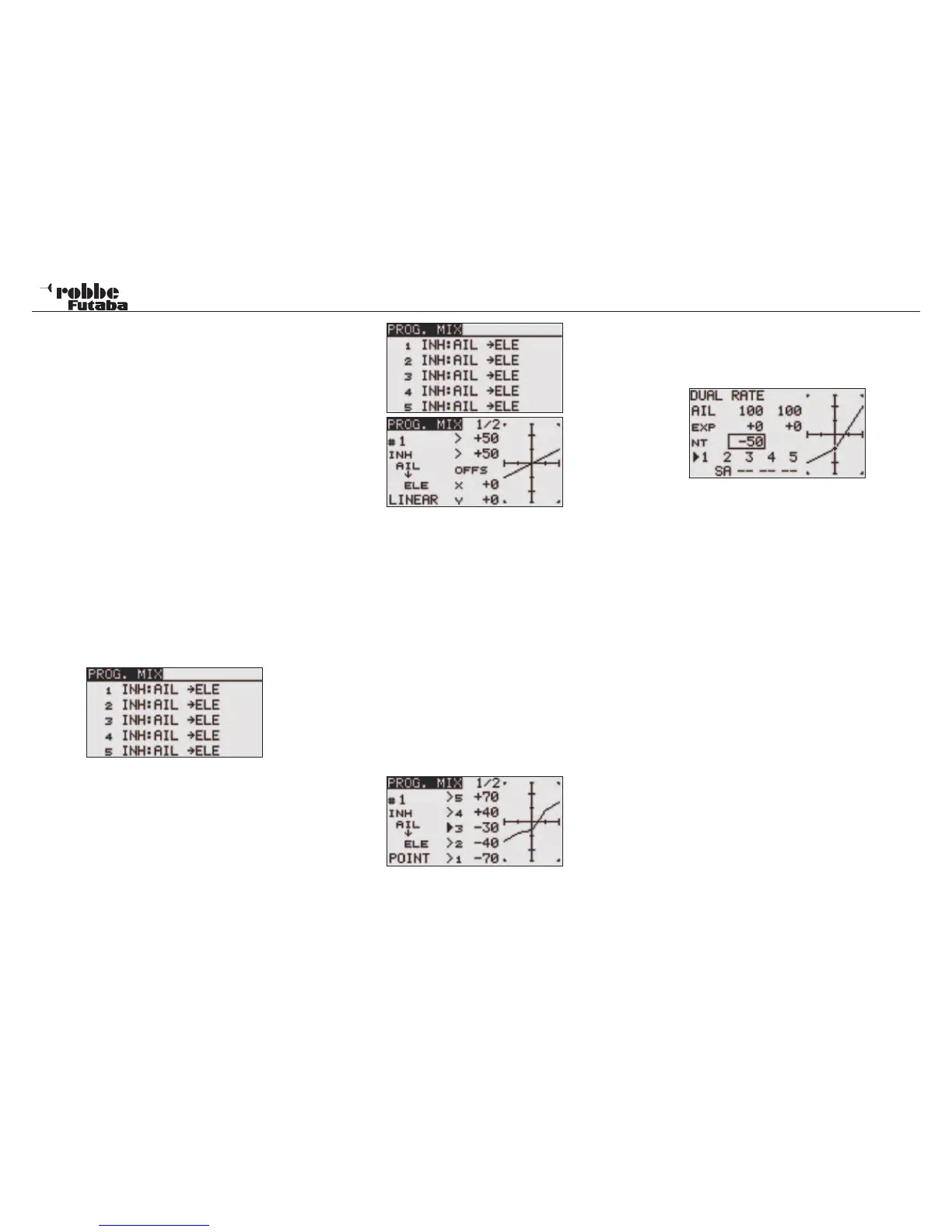
“RTN”. The Display will be as below:
The single mixers will each be listed in a line. The Display lists
five mixers. The programming process will be illustrated using
the 1 mixer. Mixers 2 to 5 will be programmed in the same
manner.
One gets to the Programming masks, in that one highlights
the required mixer and presses the ‘RTN’-key. The Display
changes and the first mixer programming menu will be displa-
yed. There are two levels, and the page counter in the middle
show which page is active. The programming consists of the
following steps.
• Activate Mixer
Move the Cursor to the item “INA’ in the second display.
Rotate the “CAP TOUCH SENSOR“ to the left will activate
the mixer; ‘ACT’ will flash in the display. “RTN” will now
close this procedure.
• Assign Mixer switch
Move the cursor in the second display to the ‘--’ item and
press the ‘RTN’-key. The switch selection menu will now
appear. Select the switch and its operating direction. If the
mixer should be permanently switched on, keep the initial
‘--’ item unchanged.
• Mix percentage and mix curve adjustment
The curve type must be initially selected. There are two
modes to choose from- “LINEAR“ or “CURVE“. With the
Linear settings, two points may be adjusted. In the curve
setting, a 5 individual point curve may be set. Highlight the
item required from “LINEAR“ and “CURVE“ and select the
desired choice.
• Master channel setting
Use the following method to set up a normal mixer. High-
light the item to the right of “MASTER“. By using the “CAP
TOUCH SENSOR“ you can select the function that will act
as the Master-Channel. When you would like to select a
switch or another control to activate the function, then you
must use the setting “H/W SELECT”. The selection is con-
firmed by pressing “RTN”.
When you would like to couple or link this mixer with another,
you must select the required function in the ‘LINK’ column.
The “LINK‘- (linking-) function will be used, to be able to
couple a programmable mixer with other mix functions. When,
for example, a model is fitted with two aileron servos (each
with its own receiver output), and coupled rudder and aileron
should be made, normally only one aileron servo will be con-
trolled when moving the rudder.
• When the “LINK‘-Function is switched on, then the other
aileron servo will be “mixed in”, so that both aileron chan-
nels are controlled.
• The Link mode can be set to ‘OFF’ (Initial setting) to ‘+’ or
to ‘-’. The respective sign sets the direction again, or says
whether a mix takes place (+). Rotating the “CAP TOUCH
SENSOR” makes the change.
• Finally, you can set the Trim function. It must be defined in
which direction the trims for both channels should operate.
In the window ‘TRIM’ there is the possibility to choose from
‘OFF” or “ON‘ settings. Selecting “ON”, the Master trim also
works on the Slave channel. Otherwise both channels are
separated. After highlighting the item, changing the mode
is made with the “CAP TOUCH SENSOR“ and confirming
with the ‘RTN’-key.
• OFFSET X and Y setting
The OFFSET Position defines the point at which the
(MASTER) control position is active.
• Slave channel setting
Programming is made with the same procedure as the
Master channel. Highlight the item to the right of the
“SLAVE“, select with “CAP TOUCH SENSOR“ and confirm
with “RTN”. When required, finally activate the linking mode
as described above
Model menu
36