FX-20
11.15 CROW/ BUTTERFLY MIXER
(Only for Glider model type)
This menu
f u n c t i o n
is used to
quickly slow
the aircraft
and reduce
altitude by si-
multaneously
raising the left
and right aile-
rons and lowe-
ring the flaps
(camber flap,
brake flap).
It is useful
when landing
fast models in
small areas.
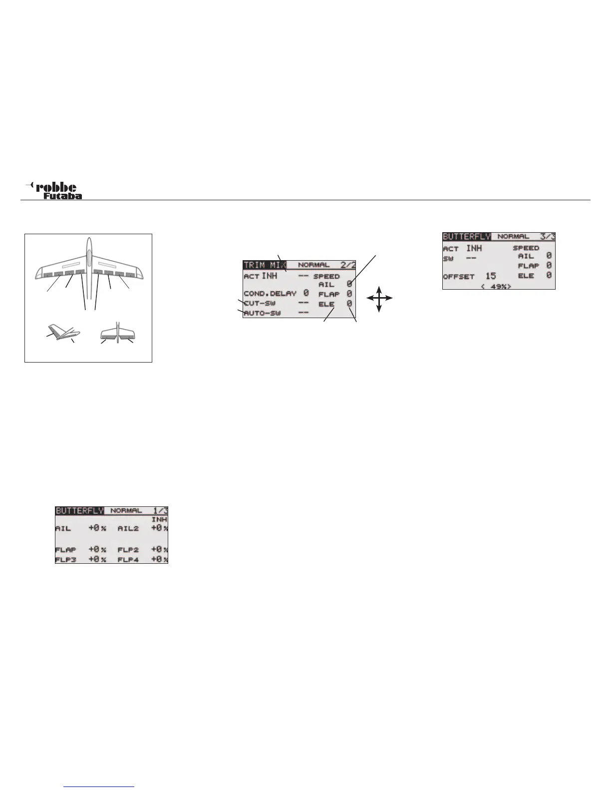
With a 6-flap wing the programming can be made so that all
flaps work as airbrakes. A switch may be freely assigned to
activate the function. It is also known as Crow Braking.
The speed of operation (SPEED) of the aileron, flap and eleva-
tor servos and the Offset where the mix becomes effective may
be programmed individually. Also this menu allows the diffe-
rential reduction of the ailerons to be programmed as needed.
Highlight the ‘BUTTERFLY’-Option in the Model-Menu with the
“CAP TOUCH SENSOR“ and confirm with “RTN”.
The Display has three sub-menus as follows:
Throw adjustment of the Aileron-Flap-Airbrakes
for the Butterfly function.
Im oberen Bereich der Ebene (2/3) wird der Zumischanteil für
den Höhenruderausgleich eingestellt. 100% Rate entspricht
ca. 25° Servoweg. Als Richtwert, schlagen wir 50% = 12,5°
Servoweg vor.
Elevator Compensation Dead-spot
Y
X
Elevator trhrow Offset
In the lower part of the Display, a 2-point curve is activated at
the factory for the elevator compensation mix.
This can be extended to be a 3 point curve, to configure a non
linear elevator mix.
Some models need a larger elevator compensation to start
with, followed by a reducing elevator compensation mixing,
other models will require totally the opposite control compen-
sation.
To activate the 3-Point Curve zu, select item X (--) and press
„RTN“ for approximately 1 second. The middle value will be
stored and shown in the Display.
Thereafter,the middle point of the 3 Point Curve can be adju-
sted using the „X“ and „Y“ values.
It will appear at first that the elevator rate and the maximum
value for the 2 Point Curve cancel each other out. In the 3 Point
Mode, there is, however, the advantage that one can quickly
change the mix ratio, without having to change the found curve
form.
Note:
If the Offset point in an existing 3 Point Curve is changed, the
previously programmed curve will be automatically deleted and
a standard 2 Pont Curve displayed!
Always take great care to check the settings!
The third menu (3/3) will activate the Butterfly mixer by selec-
ting from the ACT/INH field.
In the ‘SW’ cell, a switch can be assigned and its operating
direction defined in H/W SELECT menu. The pre-set condition
of the Butterfly mixer will always be turned on when the display
is set to ‘--’.
The ‘OFFSET’ field is used to define the stick position where
the mixer becomes active, i.e. the stick position may be stored
as a %-age value, from which the wing flaps will start to move
to the Butterfly-Position. The mechanical stick movement has
no effect (a dead area with no servo movement) up to the pro-
grammed Offset Point
This Offset point is also effective in the elevator compen-
sation.
Set the operation point for this mixer by moving the Airbrake
(Throttle) stick to the required position and press return. The
stick position will be stored and displayed in the OFFSET field
of the Display.
Similarly, the operation speed of the aileron, flap and elevator
servos when operating the mixer can be individually program-
med.
Finally, it should be noted that the programming possibilities
and the Display differ according to the chosen model- as well
as the wing type (number of servos) selected in the Linkage
Menu.
Model menu
42
Main
Aileron
(AIL1)
Camber
Flap
(FLP)
Camber
Flap
(FLP2)
Main
Aileron
(AIL2)
Flaps (FLP3 & 4)
ELERUD ELE2
ELE
V-Tail Ailvator
3-Point
2-Point