FX-20
The previous made setting can be reset
to factory setting (0 steps), when “RTN” is
presses for at least 1 second.
10.8 SERVO REVERSE
This function electronically reverses all servo directions. This
means that the servos can be installed in the model without
having to think about their rotation. Before you program the
model further, you should first set the servo direction to suit the
control sense of the model.
Select “REVERSE” in the linkage menu and access the set up
screen by pressing “RTN”.
The servo directions are displayed as either ‘NORM’ or ‘REV’.
To reverse a servo, highlight the channel with the “CAP
TOUCH SENSOR“ and press “RTN”. Scroll the “CAP TOUCH
SENSOR” to select the servo direction. Following this, rotate
the sensor to change from ‘NORMAL’ to ‘REV’ or vice versa.
Pressing ‘RTN’-key will complete the servo reversing opera-
tion.
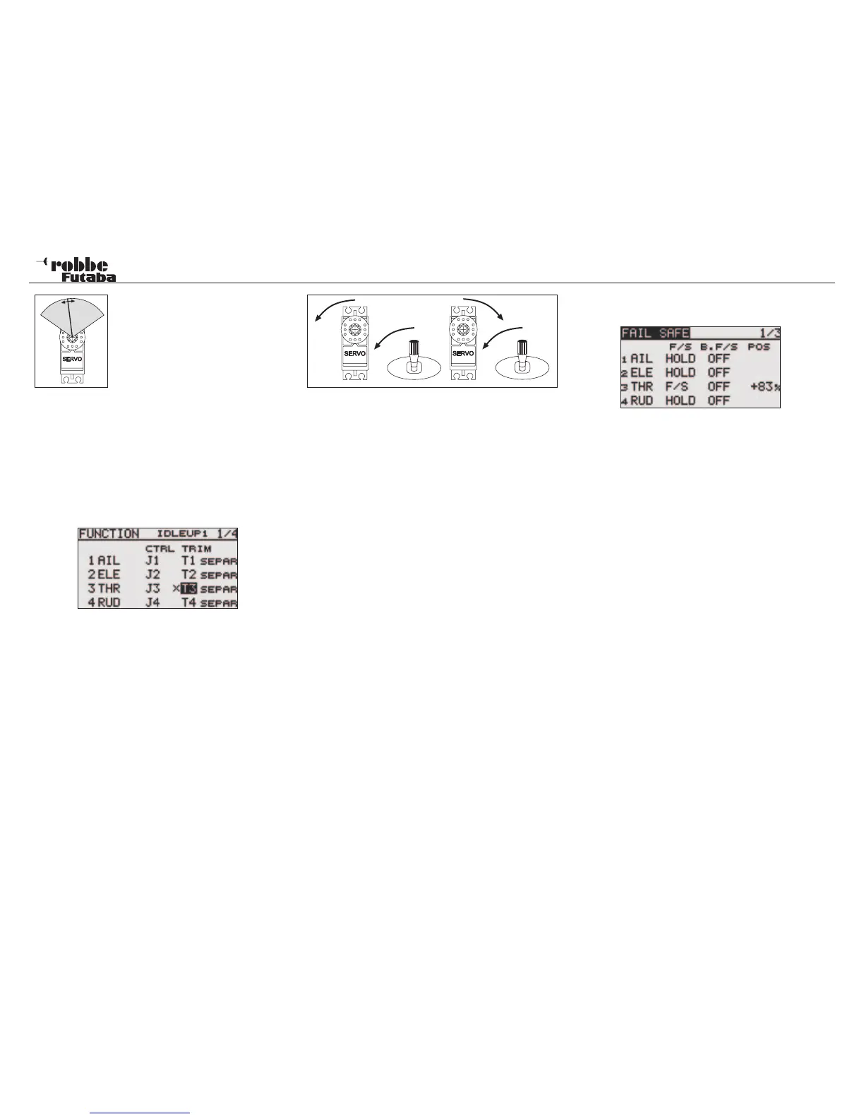
The illustration shows the normal and reversed servo direc-
tions.
Note:
Reversing the servo direction will also change the direction of
the associated trim lever.
10.9 FAIL-SAFE SETTINGS
In 7 CH operation, the Failsafe Function is limited to chan-
nel 3 (throttle) and cannot be changed. In „MULTI“ operation,
channels 1-8 are all freely assignable for failsafe position. The
following settings can be made:
1. HOLD‘-Mode: The receiver stores the last good impulse
and in the case of interference sends this signal to the ser-
vos. The servos will maintain this last “good” position until
the radio interference ceases. This mode is a factory pre-
set.
2. (F/S) Fail-Safe: The servos will move to a pre-determined
position, programmed from the transmitter and stored by
the receiver.
3. Furthermore, there is the “Battery-Fail-Safe”-setting. In
7CH operation, the B/FS is pre-set and cannot be turned
off. So that the model remains under control in the case
of B/FS, a reset switch must be defined. As soon as the
receiver battery voltage drops below 3,8 V, the selected B/
FS servos with a set F/S position, will move to their defined
position to warn the pilot that the receiver battery is almost
empty and must be landed immediately.
Fail-safe setting recommendations: Power models:
Motor to idle position and controls to fly a curve, for gliders:
Camber-, landing flaps or airbrakes/spoilers deployed. With
Helicopters, one should think about exactly whether and with
which F/S position is best for the throttle channel. A setting of 80
% throttle is a good point so that the helicopter can still hover.
However, with an electric helicopter, there is a real danger if
the transmitter is accidentally turned off, that the helicopter will
take off without pilot control. A setting of approximately 20%
minimizes this “free-flight” with interference, however the heli-
copter will still crash!
2,4 GHz operation has a very high interference rejection,
and the Hold-Mode in Heli Mode is the better alternative!
Highlight ‘FAIL SAFE’-Option with the „CAP TOUCH SENSOR“
in linkage menu and confirm choice with “RTN”.
This menu has a sub-menu for channels 5 to 8, the page
number shows these. Highlight the “F/S” item of the chan-
nel to be set with the “CAP TOUCH SENSOR“. Scrolling the
“CAP TOUCH SENSOR to the left will change the setting from
‘HOLD’ to ‘F/S’ or vice versa. The display will flash and press
‘RTN’-key to confirm the selection.
For safety, always set F/S position!
To set the Fail-Safe positions. The “CAP TOUCH SENSOR“
is used to highlight the F/S-POS item of the channel to be set
on the right hand side of the display. Move the corresponding
transmitter control to the required failsafe position and confirm
with the ‘RTN’-key. The respective servo throw will be displa-
yed as a %-age. The same method is used to set all channels
to with a ‘F/S’-setting.
To revert from ‘F/S’ back to ‘HOLD’, the F/S field of the respec-
tive channel must be selected and data entry mode selected
by RTN. Scrolling the “CAP TOUCH SENSOR“ to the right will
change the setting and be confirmed by pressing the ‘RTN’-
key.
In the same way, each channel may set in “MULTI“ mode
for Battery-Fail-Safe-Programming, ‘BAT-F/S’. The display
changes from ‘OFF’ to ‘B.F/S’. The pre-set of the warning
position of the servo is made in the same way as described
above. The pre-set position is displayed as a %-age value. It is
recommended that this warn function operates on the throttle
or airbrake/flap channel.
After storing the setting, the data is sent by Autotransfer to the
receiver. This transmission can take between 30-60 seconds
(visible by the flashing LED monitor on the receiver). During
this transmission, the model must not be flown!
This Battery-Fail-Safe Function can be released with a switch.
To do this, a switch must be assigned for this job. The required
control will be displayed as “--“ in the third page of the Failsafe
30
Linkage Menu