FX-20
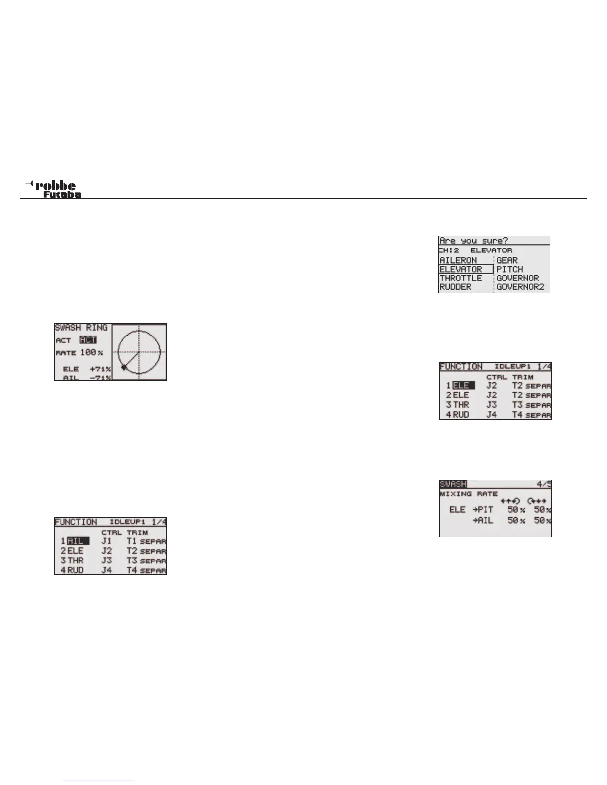
12.2 SWASH RING
The Swashplate Ring mixer limits the aileron and elevator cy-
clic pitch travel to a fixed range so that damage to the swash
linkage is prevented when using simultaneous operation of
both aileron and elevator cyclic pitch controls. This is particu-
larly useful in 3D aerobatic flight where large servo travels are
used. Selecting from the ACT/INH field in the Display activates
the function.
The operating range “ RATE“ is from 50 - 200%. If you require
to reset the range to the pre-set value of 100%, then touch
„RTN“ key for one second. The %age values for stick input are
displayed on the lower left hand part of the Display.
12.3 SWASH SETTINGS
(E.g. Type HR-3)
Individual control settings for aileron, elevator and collective
pitch. The SWASH Menu has several menu pages. The page
numbers are shown in the top right hand side of the Display.
Touching the S1-Key will leaf through the different menu pages.
You can set the Stick travel and directions of the aileron (AIL),
elevator (ELE) and collective pitch (PIT) travels; additionally
mixing rates and compensations may be programmed in this
menu.
Highlight the “SWASH” option in Linkage Menu with the “CAP
TOUCH SENSOR“ and confirm with “RTN”. The Display is as
follows:
This function is not available for Swashplate Type H-1, be-
cause the Collective Pitch function is not mixed.
Servo Neutral Adjustment
Now adjust the servo neutral position (NEUTRAL POS), this
is programmed as a %-age value. Set the mechanical neu-
trals such that the servo arms are all set to 90 degrees to the
linkages, so that the neutral position is around 50%. Move the
Collective Pitch stick to its neutral position and check that the
servo arms and their linkage are at right angles.
Stick Travel Adjustment (AFR)
The aileron, elevator and collective pitch swashplate travels
can be individually adjusted. To do this, highlight the respective
control AFR field with the “CAP TOUCH SENSOR“ and adjust
the %-age value as required. The adjustment range is between
-100% and +100%. The pre-set values are 50%. Touching the
“RTN“ key for one second will reset the values to the pre-set.
Using the function “SERVO REV” sets all the swashplate ser-
vos so that they operate in the same direction when moving the
collective pitch stick. In page 5/5, change the + or – signs to set
the servo direction for aileron and elevator so that they operate
in the correct control sense. Set the largest mechanical throw,
but not so large that the linkages bind the servo travel. Check
the maximum Collective Pitch, Aileron and Elevator functions at
the limits of control. Depending upon the swashplate type and
style of rotor head, if too much throw is available, the swash-
plate may bind and then limit the travel with the Swash mixer.
Mixing Rate setting
The HR3 swash-plate type will be used as an example to
describe mixing rate setting. The mixing used in other swash
modes may be different, however, the setting procedure is the
same.
Set the throttle stick to the preset neutral point. Adjust the
length of the linkage rod so that the swash plate is horizontal
at this position. The sub-trim function can be used to make
small adjustments.
Adjust so that the pitch curve is a straight line and the heli-
copter achieves maximum pitch. Move the cursor to the item
you want to adjust and touch the RTN button to switch to the
data input mode. Touch the RTN button to end adjustment and
return to the cursor mode.
Adjust the AIL to PIT rate so there is no binding in the elevator
or pitch movement when the aileron stick is moved to the left
and right.
Adjust the ELE to AIL and ELE to PIT rates so there is no bin-
ding in the aileron or pitch movement when the elevator stick
is moved up and down.
Adjust the PIT to AIL and PIT to ELE rates so that the swash
plate moves to the level/ horizontal position when the throttle
stick was moved to maximum low and full high.
This sub-menu compensates for the mechanical interaction
caused by the different linkages.
Set the throttle to the lowest position. Move the aileron stick to
the left and right and adjust the aileron compensation amount
on page 5/5 so that interaction in the elevator or pitch direction
is minimal.
Adjust by scrolling the CAP TOUCH SENSOR. The left and
right sides can be adjusted individually.
If the interaction increases when the compensation amount
was increased, make adjustments with the compensation di-
Linkage menu helicopter
51