FX-20
86
In RC model cars the servos are usually fitted in the openings
provided for them in the RC installation plate. Robbe quick-
release servo mounts are a good choice for model boats. Ple-
ase take great care over mounting servos, as they are sensi-
tive to vibration.
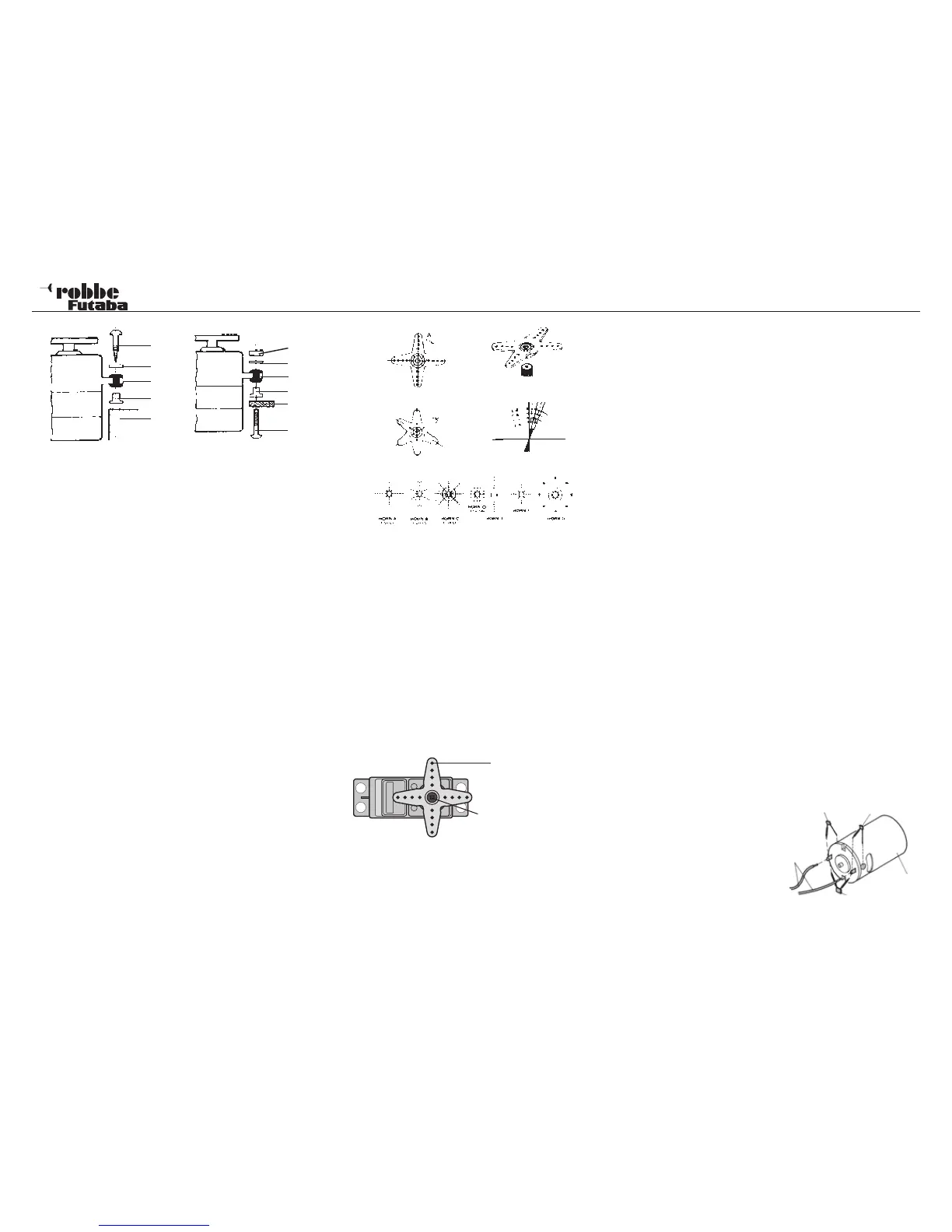
16.6 SERVO TRAVEL / SERVO OUTPUT LEVERS
The crown-gear servo-lever facilitates mechanical adjustment
of the neutral position.
Setting the neutral position
Remove fixing screw of driving lever, lift off lever, refit in
required neutral position and retighten screw.
Effect
For the smallest possible adjustment (3.6°) to the RIGHT,
ARM 2 of the 4-armed servo-lever has to be placed on the
closest possible position of base line A so that arm 3 is adju-
sted by 7.2° and arm 4 by 10.8°. For the smallest possible
adjustment of the LEFT, ARM 4 has to be placed on the next
position of base line A.
Division
The gear shaft and gear drive lever are divided into 25 seg-
ments. Therefore, any change of setting amounts to 360°: 25
= 14,4°/segment. The minimum adjustment depends on the
number of lever arms. For a 4-armed lever, this minimum adju-
stment amounts to 360° : (25 x 4) = 3.6°, for a 6-armed lever
this equals 2.4°. ARM 2 can be moved by 2.4° to the right,
ARM 3 by 4.8° to the right, ARM 6 by 2.4° to the left, ARM 5
by 4.8° to the left, ARM 4 by 7.2° to the left and right.
A range of different servo output arms is available for robbe
servos, and they are illustrated in the picture at the bottom
of the page. The drawing also shows the angular change per
individual spline segment.
16.7 INSTALLING PUSHROD LINKAGES
The basic rule when installing mechanical linkages and control
surfaces is that they must be extremely free moving, otherwise
the servos will draw excessive currents, and the effective ope-
rating time per battery charge will be greatly reduced. At the
same time the centring accuracy of the control system will be
worse, which in turn has a negative influence on the model’s
flying characteristics.
4
5
6
1 Nut
2 Washer
3 Rubber grommet
4 Metal spacer sleeve
5 Placa de aluminio
6 Tornillo
1. Woodscrew
2. Washer
3. Rubber grommet
4. Metal spacer sleeve
5. Madera
1
2
3
1
2
3
4
5
Retaining screw
Pushrod
17. THE SYSTEM IN USE
All robbe-Futaba receivers continue to work with full range at
reduced voltage, down to the point where the supply voltage
falls to 3 V. The advantage of this feature is that the recei-
ving system will normally continue to work even if one cell fails
completely (short-circuit), since robbe-Futaba servos still work
down to 3.6V, albeit at slightly lower speed and with reduced
power. This is very important in winter, when ambient tempera-
tures are very low; otherwise any momentary voltage collapse
could cause the loss of a model. However, there is a drawback:
under certain circumstances the user may not even notice the
failure of a battery cell. For this reason it is important to check
the receiver battery from time to time. We especially recom-
mend the use of robbe battery monitors, No. 8409, which indi-
cate the condition of the battery by means of a chain of LEDs.
17.1 POWER-ON SEQUENCE
Always switch the transmitter on first, and only then the re-
ceiver; reverse the sequence when switching off. When you
switch the receiver on, the servos run to the neutral position.
We recommend that you check each function in turn by ope-
rating the associated stick or other transmitter control. Check
that each control surface operates in the correct “sense” (di-
rection) relative to the stick movement. If any control surface
moves in the wrong direction, that servo must be reversed at
the transmitter.
17.2 ‘ELECTRICAL NOISE’ INTERFERENCE
If your radio control system is to operate safely and reliably, it
is essential to avoid what is known as electrical ‘noise’ inter-
ference. This problem is due to metal parts - such as push-
rods - rubbing against each other intermittently as a result of
vibration. For this reason the linkage to the engine’s carburettor
must always terminate in a plastic clevis - never connect a
metal linkage directly to the carburettor arm without an insula-
tor between them.
17.3 ELECTRIC MOTORS
All conventional electric
motors in RC models must
be effectively suppressed,
otherwise the sparks which
are generated between the
armature and the carbon
brushes when the motor is
running will have a serious
adverse effect on the radio
47 nF
100 nF
Electric
motor
Power
connec-
tions
100 nF