FX-20
10.6 FUNCTION
When you choose the model and wing types, you will find that
optimized combinations of servo channels and control inputs/
functions have been factory preset for the model type selection.
We recommend that you keep these, wherever possible, so
that a common allocation of controls to their respective servo
functions is maintained.
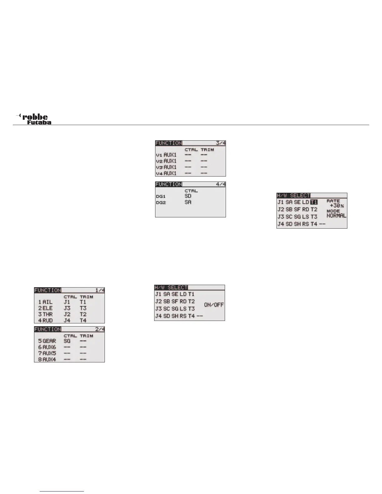
The “FUNCTION” menu will display an overview of which re-
ceiver outputs, their respective servos and which transmitter
control input operates them. Functions with 2 or more servos
are already configured with the appropriate transmitter con-
trol input mixing. The configuration varies only slightly within
a model type and, the number of allocated channels will be
dependent upon the number of controls and flaps.
This differs when changing model type. If the model type is
changed from a conventional to one with two elevator servos
(Ailvator), this changes the channel allocation of the functions.
This also applies, naturally, for gliders, with and without motors,
and also for tail-less models with and without winglets.
TRANSMITTER CONTROL ASSIGNMENT
Select “FUNCTION” in the Linkage menu with the “CAP
TOUCH SENSOR“ and confirm with “RTN”. There are further
adjustments of this type and the page number on the right hand
side of the display shows these. In this menu, you can change
the control input and trim assignment for all functions and de-
fine a function order. The following displays appear:
Multiple control functions can be assigned to a chosen
control input. Also, the channel settings may be freely
modified.
• Select the required control input. . Move the cursor to
the ‘CTRL” field in the “FUNCTION” menu with the “CAP
TOUCH SENSOR” and select with “RTN”.
• Now assign the required control for this function. A new
control selection menu, “H/W SELECT” will appear which
shows all the individual transmitter controls as symbols.
• In this display, move the flashing cursor to the control input
you wish to assign with the “CAP TOUCH SENSOR“ and
select with ‘RTN’-key.
SELECTION/ASSIGNMENT OF TRIM CONTROLS
The trim buttons are freely selectable. The method is identical
to control input assignment. Highlight and confirm the ‘Trim’
field of the required function, the trim set up screen is displa-
yed.
In this menu the symbols may be selected and allocated on the
left hand side of the display.
TRIM SETTINGS
This menu allows further adjustments to be made:
Trim Rate
The adjustment range of trim throe can be made from -150 to
+150% of the control throw. The factory preset value is +30%.
After highlighting and activating this option, scrolling the ‘CAP
TOUCH SENSOR’ can be used to set the required %-age
value. Pressing ‘RTN’-key for one second will reset the value
to factory preset (30%).
Trim Mode
Move the cursor to “MODE” and confirm with RTN. By scrol-
ling the “CAP TOUCH SENSOR“, the following modes can be
accessed.
Normal = Normal mode, with the trim operating equally
around the neutral point. The selected trim range will operate
in the centre but extend the end point throw also.
ATL = Asymmetrical trim limit, changes the trim value only at
one end of the control throe, and is used mostly for the throttle
function, when it is desirable to control the idle trim without
affecting the full throttle position.
ATL Normal/Reverse = Umpolung der ATL Trimmwirkung
oben/unten bzw. vorn/hinten.
28
Linkage Menu