FX-20
11.16 TRIM MIX
The FX-20
S o f t w a r e
has a TRIM
MIX function,
which adjusts
the trim offset
rates of the ai-
lerons, eleva-
tors, and flaps
(camber flaps,
brake flaps)
according to
the flight con-
dition. For
example, this
function can
be set up for
glider launching, with speed flaps and ailerons drooped, and a
slight amount of up elevator, and can be used for high speed
flying, with both ailerons and speed flaps reflexed upwards
slightly, and will have also some elevator compensation. To
prevent sudden trim changes when switching flight conditions,
a delay can be set to provide a smooth transition between
the two conditions. It is also possible to program a cut switch,
which will turn off the delay. Furthermore, the Software allows
you to assign an auto switch, which will link the trim mix to a Tx
stick, switch, or knob. Additionally, the operation speeds of all
the aileron, elevator, and flap servos (dependent on wing type
selected in Model Type in the Linkage Menu) can be adjusted
individually to avoid sudden trim changes when operating the
mix.
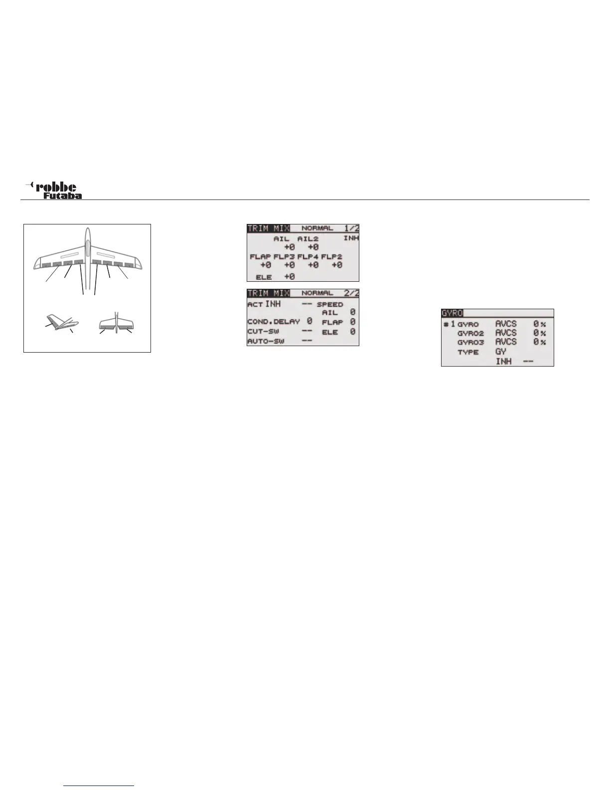
Select the TRIM MIX Option in Model-Menu using the “CAP
TOUCH SENSOR“ and confirm with “RTN”. The Display has
two sub-menus as follows:
The first Menu programs the pre-set throws of the aileron, flaps
and the elevator compensation. For each servo, an Offset-Va-
lue is set, by scrolling to the respective servo field in the Dis-
play and setting the throws with the “CAP TOUCH SENSOR“
and confirm with “RTN”.
In the second menu page, selecting ‘ACT/INH’ activates the
Mixer. The Display will show ON or OFF depending on activa-
tion status. The “TRIM MIX“ can be manually activated via a
switch or stick switch position. Should you wish to use the stick
as a switch, highlight the field next to “AUTO-SW“ and confirm
with “RTN”. The H/W SELECT menu will allow any of the four
sticks, (J1…. J4) to be assigned as a switch and the operating
point defined.
The servo speed can be programmed in the second menu
page for all flap settings of aileron, camber flaps and elevator
servos.
The “CUT-SW” may also be defined so that the condition time
delay can be switched from active to inactive. Therefore, it is
now possible to have two forms of flight condition switching on
demand, one abrupt and the other with a smooth transition.
Assignment of the switch is made with the usual method.
Finally, please note that the programming features and display
will vary according to model and wing type selected in the Lin-
kage Menu.
11.17 GYRO
This function is used when a GYA Series gyro is used to stabi-
lise the aircraft‘s attitude around a single axis. When using up
to 3 gyros, there are three modes available (#1-#3) where the
sensitivity may be programmed as a %age and called up by a
switch. The operation mode/ gyro type (Normal mode/AVCS
mode) can be changed via a switch.
Highlight and the “GYRO” option in the Model Menu using the
“CAP TOUCH SENSOR and confirm with “RTN”. The Display
is as follows:
The Menu has three identical pages for setting up to 3 different
gyros with a switched access to settings.
Also this function must firstly be activated in the ‘ACT/INH’ field.
Highlight the cell and set to ACT with “CAP TOUCH SENSOR“
and finally activate with “RTN”. Depending on switch position,
the Display will show ON or OFF.
The ‘TYPE’ cell is used to define whether the Gyro works in
‘GY’ (Heading Hold)- or in normal Mode. Further advice will be
found in the instructions of your gyro being used.
Using the normal method, a switch and its sense can be assi-
gned in H/W SELECT menu accessed via the SWITCH selec-
tion field. The preset is ‘--’, i.e., the function is always turned on.
The sensitivities for up to three possible axes of a gyro can be
set in the % age column.
Model menu
43
Main
Aileron
(AIL)
Camber
Flap
(FLP1)
Camber
Flap
(FLP2)
Main
Aileron
(AIL2)
Flap
(FLP3 & 4)
ELERUD ELE2
ELE
V-Tail Ailvator