FX-20
16.2 SWITCH HARNESS
It must be possible to operate the receiving system switch
easily, without mechanical restriction, i.e. the cutout in the
fuselage side must be large enough to avoid obstructing the
mechanism. In powered models with internal-combustion en-
gines, the switch should be mounted on the opposite side to
the exhaust, to avoid the danger of oil penetrating the housing
and soiling the contacts. If your model is fitted with a large
number of high-power digital servos, we recommend the use
of a standard commercial dual-battery power supply system.
16.3 SERVO LEADS
When deploying servo leads, please ensure that they are not
under any mechanical strain and are not kinked or bent tightly,
as this might cause them to fracture over time. Make sure there
are no sharp edges, which might damage the cable insulation.
All connectors must be firmly fitted and secure. When discon-
necting servo plugs, pull on the plastic housings - not on the
wires. Servo leads should not just be left trailing loosely inside
the fuselage; it is far better to attach them neatly to, say, the fu-
selage side or the chassis using adhesive tape or cable ties. It
is not permissible for modifications of any nature to be made to
the receiving system components. Avoid reversed polarity and
short-circuits of all kinds, as the electronics are not protected
against such errors.
16.4 SERVO SUPPRESSOR FILTERS
If you wish to use long servo leads or extension leads, please
note that interference may be picked up via the over length
cables. Where servo cables are longer than two normal leads
(approx. 50 cm), you should at least use twisted cables (No. F
1452).Even better: use suppressor filters, No. F 1413.
16.5 INSTALLING SERVOS
When installing servos in a model, always use the rubber
grommets and tubular brass spacers (eyelets) supplied. When
you fit the servo retaining screws, ensure that they are not tig-
htened beyond the point where the brass eyelets make contact
top and bottom; if the rubber grommets are compressed to this
point; they are no longer capable of absorbing vibration.
• The range may be reduced by a maximum of 20%. If it noti-
ceably less, then the receiver is getting interference from
the power unit. Get help to make sure whether all of the
above mentioned interference protection measures have
been made correctly
• The Power-Down mode remains active for only 90 seconds
and switches automatically back to normal operation. To
extend the Power-Down-Mode during the 90 seconds,
select the “NEW START” field with the CAP TOUCH SEN-
SOR and press the “RTN” button. The time will be extended
for a further 90 seconds.
• Should the Power-Down-Mode be required after the time
limit, and then the Tx must be switched off and on again.
The power-Down-Mode can be switched on as previously
described.
Attention:
Never take off with the Tx in Power-Down- Mode.
For safety reasons a further range test is not possible when
the Tx is already transmitting at full power. It is necessary to
turn the Tx off and on again. This measure stops an accidental
switch to range test power during normal operation.
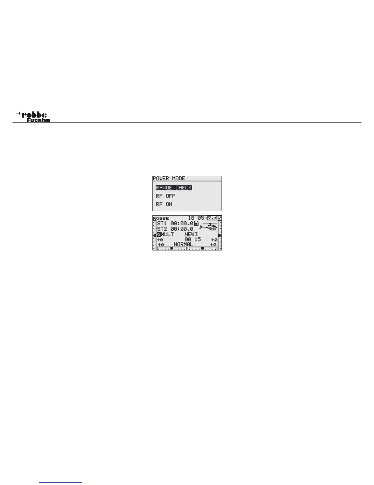
RF OFF
When using a flight simulator or programming the Tx. Battery
life will be extended and improved with the Radio Frequency
(RF) switched off. Use the following procedure.
Switch on using the same procedure as with the Range Test.
Highlight RF OFF in the lower part of the Display and confirm
with RTN. The Start Display will now be active but will show
that the Tx active is but with no RF radiating.
85