FX-20
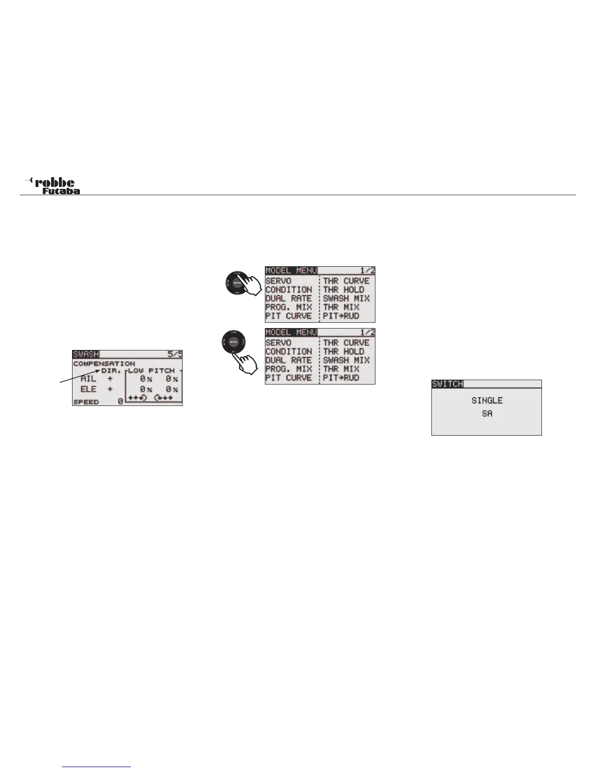
rection [DIR.] as „-“.
Adjust the elevator compensation amount so that the aileron or
pitch direction interference when the elevator stick was moved
up and down is minimal.
Repeat the above steps; perform aileron and elevator compen-
sation similarly at full throttle.
In Menu 5/5, the speed compensation (SPEED) can be adju-
sted. touch the RTN button to switch to the data input mode.
Set the throttle stick to the neutral point position. Quickly move
the elevator stick and adjust the speed compensation amount
[SPEED] for minimum interference in the pitch direction.
direction
Adjust by scrolling the “CAP TOUCH SENSOR” and high-
lighting to adjust the settings. Touch the RTN key to return to
the cursor mode.
13. LINKAGE-MENU (HELICOPTER MODELS)
This section deals with the helicopter specific menus within
the Linkage Menu. To activate Heli Mode, the HELICOPTER
Model Type must be selected in Linkage Menu and confirmed
by touching “RTN”. A summary of all the Heli-specific Model
Menus will be displayed:
• SERVO: Servo throw display see page 22
• CONDITION: Idle Up selection
• DUAL RATE: Second control throw curve see
page 34
• PROG. MIX: Programmable Mixer see page 35
• PIT CURVE: Collective pitch settings
• THR CURVE: Throttle curve settings
• THR HOLD: Throttle Hold/Autorotation settings
• SWASH MIX: Swashplate mixer
• THR MIX: Swash-> Throttle Mixer
• PITCH -> RUD: Pitch -> Tail rotor Mixer
• GYRO: Gyro settings
• GOVERNOR: Rotor head speed governor
• FUEL MIX: Carburetor mixture adjustment set-
tings
13.1 FLIGHT CONDITION (IDLE UP 1, 2 &3/ HOLD)
The Software of the FX-20 has five different flight conditions
per model memory. For the different flight tasks, one can store
the optimized settings. When required, a switch can be used to
activate the flight condition required.
This option allows gyro, rotor speed and control throws to be
varied and accessed by a switch to suit the flight condition.
If several flight conditions are set up for one model, the prio-
rity may be freely assigned. The flight conditions may also be
copied and a delay time may also be programmed for each
channel, so that a soft transition is made when switching flight
condition, without a major trim change occurring.
Highlight “CONDITION” in the Model Menu with the “CAP
TOUCH SENSOR“ and confirm with “RTN”.
The programming process contains the following steps:
• SINGLE / LOGIC Switch
If more than one flight condition has been programmed, the
operational priority may be customized to use Logic switches
to activate the flight conditions. The following functions are
available for use:
• AND: Serial connection of the switches e.g. “SA AND “SB“
activate the flight condition.
• OR: Parallel connection of the switches e.g. “SA“ OR „SB“
activate the flight condition.
• EX-OR: Either -Or connection and exception of specific swit-
ches e.g. EITHER “SA“ OR “SB“ activates the flight
condition.
Model menu helicopter
52
2 x
1x