FX-20
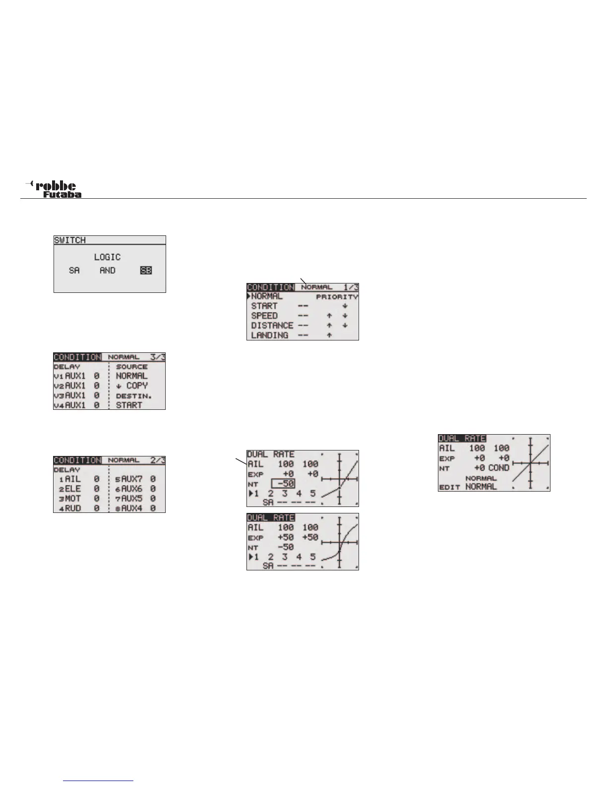
• EX-OR: Either -Or selective coupling or exclusion of defined
switches. E.g. EITHER “SA OR SB“ activates the
function.
• COPY FLIGHT CONDITION
Move the cursor to the original flight condition (SOURCE)
that you wish to copy. Select the Destination (DESTIN)
item to which you wish to copy into. Move the cursor to the
(COPY) item and press ‘RTN’-key for at least 1 second.
The Flight Condition is now copied.
• CONDITION DELAY SETTING
Select the condition that you want to set. Then select
‘DELAY’ and confirm with ‘RTN’-key. The Display will be as
below:
Use the “CAP TOUCH SENSOR“ and highlight the ‘DELAY’-
column of the channel that you wish to adjust the delay time.
The delay time is made by rotary scrolling the “CAP TOUCH
SENSOR“. The adjustment range is between 0 and 27 steps.
The initial value is set to ‘0’, that means that no delay is pro-
grammed.
• PRIORITY CHANGE
Highlight the flight condition that you wish to change priority
using the “CAP TOUCH SENSOR“. Using the “CAP TOUCH
SENSOR”, the highlighted flight condition can be moved by
using the Up-Arrow and Down-Arrow to change the priority.
The last condition becomes the highest priority.
Active Flight Condition
11.3 DUAL-RATE
Up to five different Dual-Rate throw adjustments (second swit-
chable control travel) with different throw and curve characteri-
stics and / or differing Exponential curves. A maximum of four
may be controlled with one switch. Highlight “DUAL RATE“ and
select with ‘RTN’-key. You may make the adjustments in the
following sub-menus.
Next you must choose the function that you wish to use. To do
this, position the cursor, on the selected line on the first item.
The throws are set separately for the right and left of servo
neutral position. To do this, highlight the throw to be set with
the ‘CAP TOUCH SENSOR.
The adjustment range is between -0% and +140%. The initial
value is +100%. Pressing the ‘RTN’-key for at least 1 second
will reset it to the initial value. Using the same method, the
settings for both exponential curves may be selected. The ad-
justment range is between -100% and +100%. The initial value
is 0%.
NT=Neutral point
Additiona to the end points and curve type (Normal/ Expo),
the Neutral point of the control input curve can be set between
(+/- 120%).
Just like an AFR Function, the control input curve can be chan-
ged from a straight line to a curve around the zero point, where
the control no longer is effective.
With Camber Flap, Spoiler and Butterfly (Crow Brake), the ad-
justment range is extended similarly to +/- 120, whereby the
control curve can be converted to a straight line over the whole
control range.
In the Helicopter and Glider menus, there is an additional
choice of using a normal switch as in Airplane menu or opera-
ted by using flight condition switching to activate this function.
Model menu
35
Function