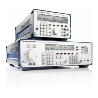
V L F > H F R E C E I V E R S
f
R & S E K 8 9 5 / R & S E K 8 9 6
User Manual
f
Cabling
e
LINE
OUTPUT
RS232C > RS485
6. Connection of a data line
(AF and FSK signals)
Connect the 25>way female connector
strip via a data line to an external device.
Fix the trapezoidal connector strip by
means of locking screws.
As the mating contact we recommend a
25>way trapezoidal male connector strip,
series D (FM 018.6430) and in addition a
protective housing (FM 627.1826).
Adjust the AF signal level (600>] line
output) via variable resistor LINE (see also
A1.6) as required (setting range >10 to
+10 dBm).
Adjust the AF2 signal level (600>] line
output) via variable resistor LINE2 (see
also A1.8) as required (setting range >10
to +10 dBm).
7. Connection of a control line
(RS232C>RS485)
Connect the 25>way male connector strip
via a control line to one of the following
devices:
> PC
> Terminal
> VLF>HF Receiver R&S EK 896
> VLF>HF Receiver R&S EK 895 with
Control Unit 1 (= R&S GB 890)
> VLF>HF Receiver R&S EK!085
Fix the trapezoidal connector strip by
means of locking screws.
For this purpose the interface parameters
of the units interconnected via the
RS232C/RS485 interface must be identical.
Set RS232C/RS485 interface parameters
acc. to A1.4, as required.
As the mating contact we recommend a
25>way trapezoidal female connector
strip, series D (FM 018.5756) and in addi>
tion a protective housing (FM!627.1827).
6164.0717.02_01
> 2.10 >

 Loading...