186
8
Main
Specications
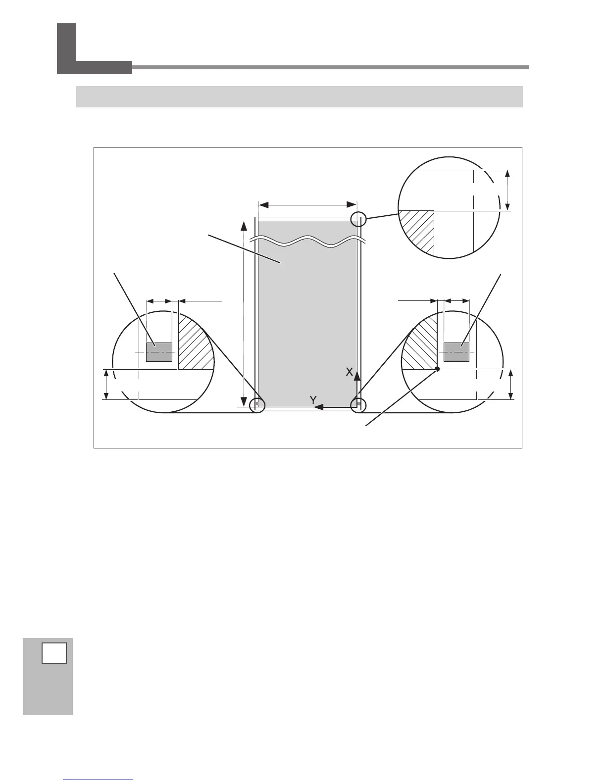
Printing/Cutting Area
Maximum Area
The printing or cutting area along the scanning direction (the direction of the head movement) is determined
by the position of the left and right pinch rollers.
(*1)
If " EDGE " or "PIECE" is selected in the [SETUP SHEET] menu.
Margin length required by the media take-up and feed systems is approximately 1,100 mm (43 in.).
Max. 24,998 mm (984 in.)
1.5 mm
(0.1 in.)
Max. 1346 mm (53 in.)
210mm (8.3 in.)
Pinch rollers [Right]
Printing or cutting area
Pinch rollers [Left]
Origin point for printing or cutting coordinates
75 mm* (3 in.) (*1)
10 mm
(0.4 in.)
1.5 mm
(0.1 in.)
10 mm
(0.4 in.)
75 mm* (3 in.) (*1)
 Loading...