1
Machine
Highlights
6
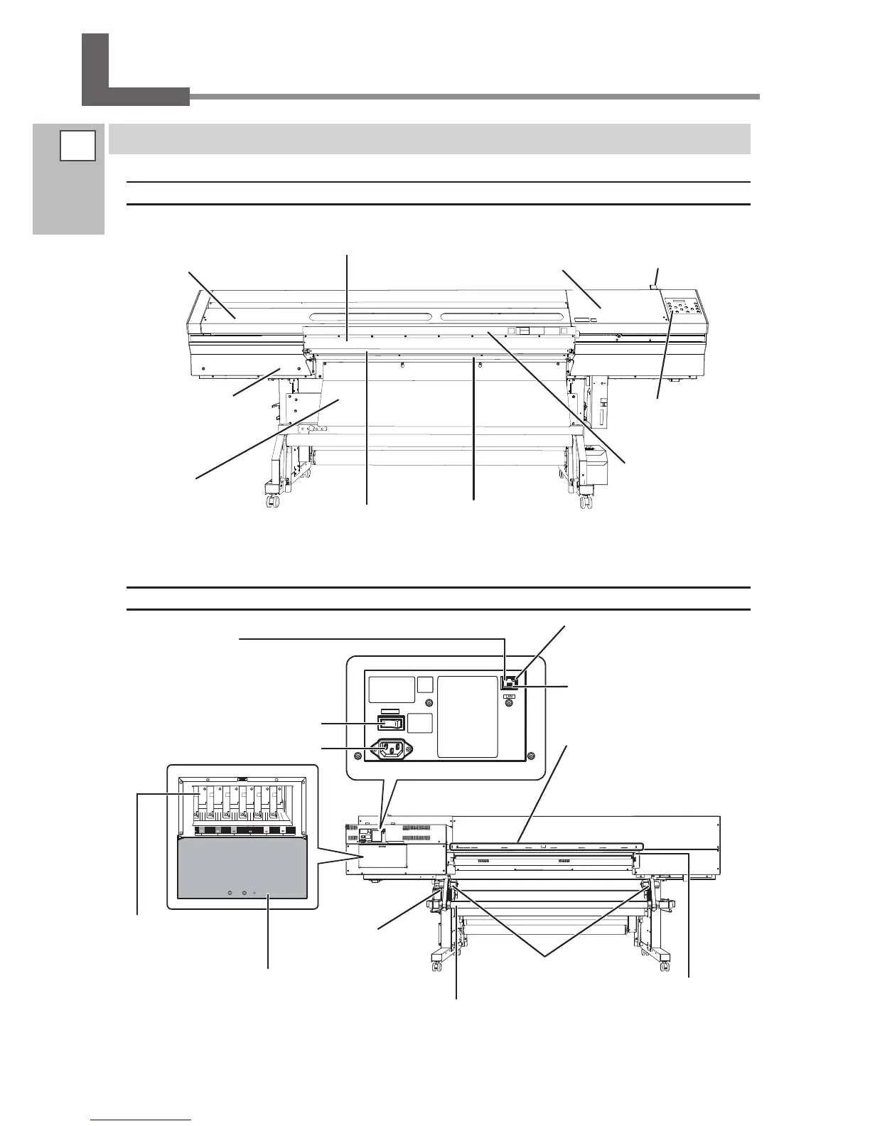
Part Names and Functions
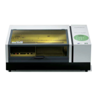
Printer Unit
Front
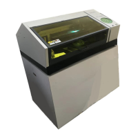
Rear
Media holders
Here is where you load
roll media and secure it
in place.
Grit patterns
These indicate the locations of the
grit rollers. You use them as guides
for positioning the left and right
sides when loading media.
Rear cover
Be sure to install
this when perform-
ing printing
Ink cartridge cover
Be sure to close this cover except when
absolutely necessary, such as when you
are replacing ink cartridges.
Air intake box
This is where air intake
is performed to lessen
the charasteristic odor
of inks. Ventilating
equipment is required
separately.
"Setup guide"
Maintenance cover
You remove this when
you perform cleaning of
the print heads.
Main power switch
Power-cord connector
Status LED
This flashes yellow while data
is being received from the net-
work.
Link LED
This lights up green
when the connection to
the network is correct.
Cartridge slots
There are where ink car-
tridges are installed.
Drain bottle
Shaft
Ethernet connector
This is used to connect the printer
to a network.
Media guide
This prevents the end of
the media from striking
the stays or other areas,
which can cause the me-
dia to come loose.
Loading lever
You operate this when
you load media.
Operation panel
P. 8, "Operation Panel"
Front cover
Be sure to close this when
you perform printing.
Side cover
You remove this when you
perform maintenance.
Media discharge port
Elastic media is discharged
here.
Media discharge port
Media is normally discharged
here.
Front table
When using elastic media,
this table is pulled out to
provide stability for media
feed.
 Loading...