90
Other Functions
Control Using the TALLY/GPIO Connector
You can use control signals inputted to the TALLY/GPIO connector via GPI to remotely control the VR-6HD from an external device.
Also, you can output tally signals or GPO control signals from the TALLY/GPIO connector.
Specication of the TALLY/GPIO Connector
Pin layout
5 4 3 2 1
1516171819202122232425 14
10111213 9 8 7 6
DB-25 type (female)
Tally output
Trigger
method
Open collector
Maximum
input
12 V/120 mA
Control input
Trigger
method
No-voltage contact (make-
contact) triggering
Contact
capacity
DC 24 V 0.1 A or higher
Input method Photocoupler
Pin assignments
Pin no. Pin name Function (default value)
1 TALLY/GPO 1 PGM VIDEO IN 1
2 TALLY/GPO 2 PST VIDEO IN 1
3 TALLY/GPO 3 PGM VIDEO IN 2
4 TALLY/GPO 4 PST VIDEO IN 2
5 TALLY/GPO 5 PGM VIDEO IN 3
6 TALLY/GPO 6 PST VIDEO IN 3
7 TALLY/GPO 7 PGM VIDEO IN 4
8 TALLY/GPO 8 PST VIDEO IN 4
9 TALLY/GPO 9 PGM VIDEO IN 5
10 TALLY/GPO 10 PST VIDEO IN 5
11 TALLY/GPO 11 PGM VIDEO IN 6
12 TALLY/GPO 12 PST VIDEO IN 6
13 TALLY/GPO 13 GPO 1
14 TALLY/GPO 14 GPO 2
15 TALLY/GPO 15 GPO 3
16 TALLY/GPO 16 GPO 4
17 GND
18 GPI 1 Not assigned
19 GPI 2 Not assigned
20 GPI 3 Not assigned
21 GPI 4 Not assigned
22 GPI 5 Not assigned
23 GPI 6 Not assigned
24 GPI 7 Not assigned
25 GPI 8 Not assigned
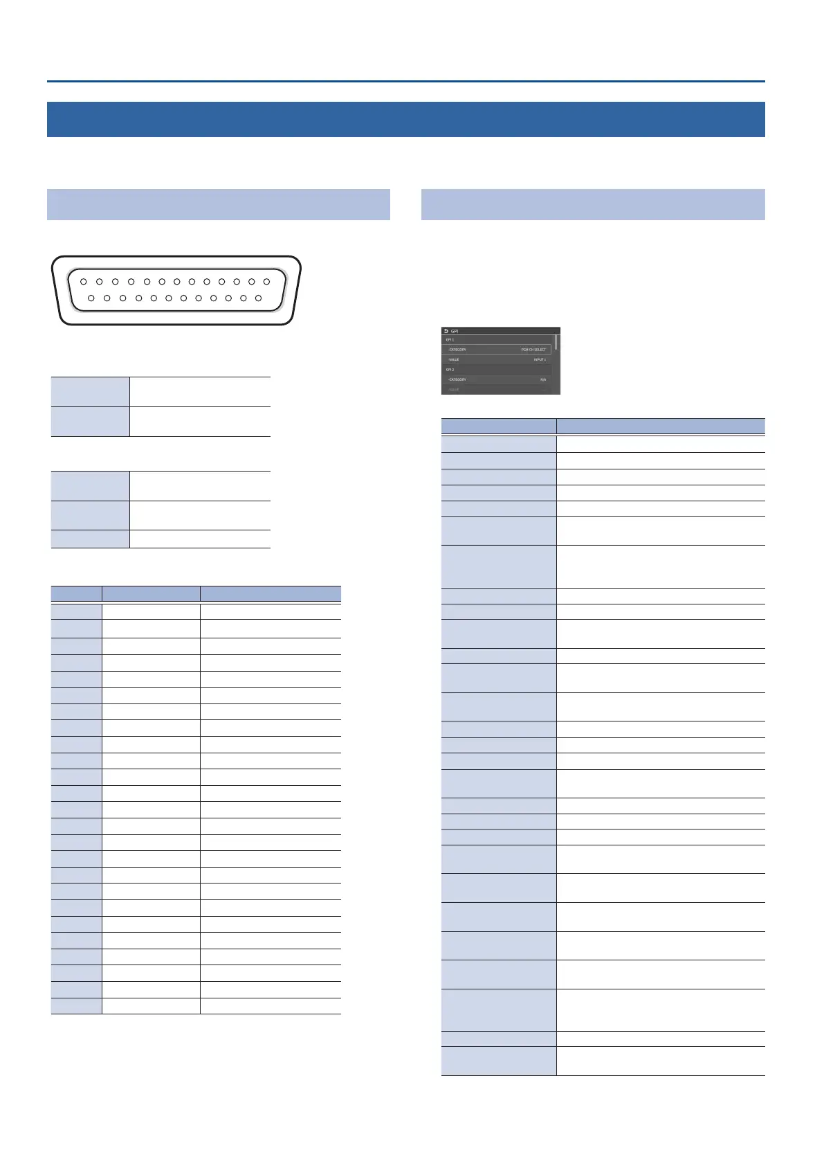
Inputting a Control Signal
When an external control signal is input, the functions assigned to GPI
1–8 are executed.
1. From the [MENU] button
Ó
“REMOTE”
Ó
“GPI”
Ó
select GPI
1–8 “CATEGORY” or ”VALUE”, and press the [VALUE] knob.
2. Use the [VALUE] knob to select the functions assigned to GPI
1–8, and then press [VALUE].
ÁCATEGORY
Value Explanation
N/A No function is assigned.
PGM CH SELECT
Switches the video sent to the PGM bus.
PST CH SELECT
Switches the video sent to the PST bus.
AUX CH SELECT Switches the video sent to the AUX bus.
INPUT 1–6 ASSIGN Changes the video assigned to INPUT 1–6.
STILL OUTPUT
Pauses the normal output, and previews or
nal outputs a cut of the still image.
VIDEO PLAYER
OUTPUT
Temporarily pauses the normal output, and
previews or nal outputs a cut of the video
player’s video signal.
PinP & KEY 1–2 SOURCE
Switches the video source of the inset screen.
DSK SOURCE Switches the DSK video source.
BUTTON CONTROL
This works the same as when you press the
button selected in “VALUE”.
AUDIO INPUT MUTE
Turns the mute function on/o for the input audio.
AUDIO OUTPUT MUTE
Turns the mute function on/o for the
output audio.
AUDIO INPUT SOLO
Turns the solo function on/o for the input
audio.
AUDIO OUTPUT SOLO
Turns the solo function on/o for the output audio.
VOICE CHANGER Turns the voice changer function on/o.
AUTO MIXING Turns the auto mixing function on/o.
REVERB(MOMENTARY)
Reverb turns on only while a control signal
is input.
REVERB(ALTERNATE) Turns reverb on/o.
OUTPUT FADE The nal output video fades in/out.
LOAD MEMORY Recalls a scene memory.
INPUT SCAN
Each time a control signal is input, the INPUT
1–6 video changes in order.
SCENE MEMORY SCAN
Each time a control signal is input scene
memories 1–32 are recalled in order.
PinP & KEY 1–2 SCAN
Each time a control signal is input, the PinP &
KEY 1–2 inset screen videos switch in order.
DSK SCAN
Each time a control signal is input, the DSK
caption video changes in order.
MACRO EXECUTE
Executes a macro (a series of recorded
operations).
SEQUENCER
When the sequencer function is on, this
works the same as when you press the
button selected in “VALUE”.
GPO (ONE SHOT) Outputs a control signal for 0.5 seconds.
GPO (ALTERNATE)
The control signal output is switched on/o
each time a control signal is input.
ÁVALUE
Congures the detailed settings related to “CATEGORY”.
 Loading...