Fieldbus Interface
PR 5220 Instrument Manual
EN-140 Sartorius
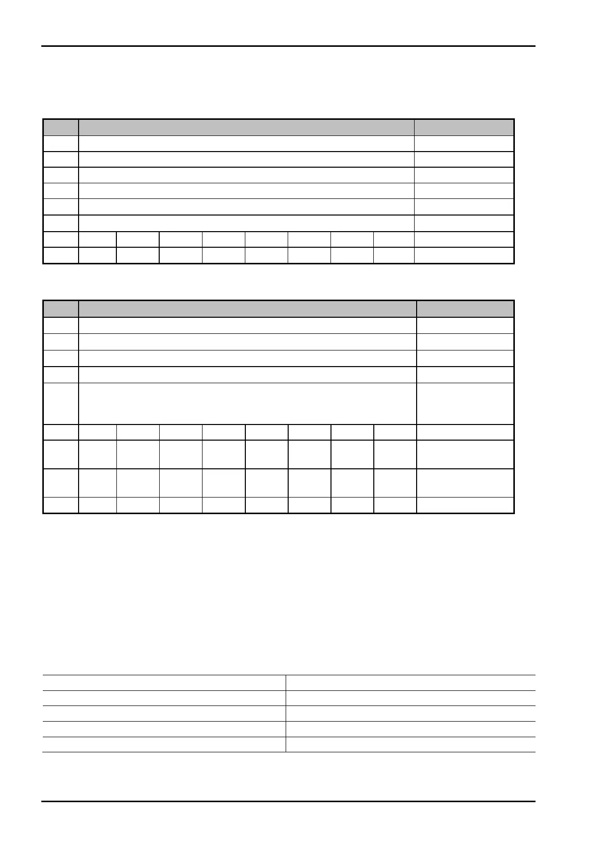
Example: Reading the Gross Weight
The master writes value 8 in
Read_Value_Select (byte 4) of the input area.
Input area
Byte Value Description
0
1
2
3
4
8
Gross
5
The master waits, until value 8 was reflected in Read_Value_Selected (byte 4) of the output area.
Output Area
Byte Value Description
0
00
Gross value
1
00
"
2
4
"
3
D2
"
4
8
Gross weight
request was
detected
5 Status
6 Test
active
Command status
7 Stand-
still
Inside
ZSR
Center
zero
Below
zero
Over-
load
Above
Max
Adc
error
Device status
Bit 7 Bit 6 Bit 5 Bit 4 Bit 3 Bit 2 Bit 1 Bit 0
The gross value (hex:000004D2 <=> 1234) can be read from bytes 0...3. When the 'Overload', 'Test Active' or
'ADC error' bits are set, the read value is invalid.
Negative values are output in two’s complement.
7.3 Special hints for DeviceNet and EtherNet-IP
With these field bus types, the sequence of the bytes (only applicable for words and individual bytes) is
inverted.
With long words, this problem does not arise due to compensation by the firmware.
Sequence of bytes 0…3, e.g. with device type and software version, see table:
Standard sequence Sequence for DeviceNet and EtherNet –IP
Byte 0 TYPE MSB Byte 0 SUBVERSION
Byte 1 TYPE LSB Byte 1 MAINVERSION
Byte 2 MAINVERSION Byte 2 TYPE LSB
Byte 3 SUBVERSION Byte 3 TYPE MSB
Consequently, the sequence on the PLC side must be changed when using the DeviceNet and EtherNet –IP field
bus types.
 Loading...