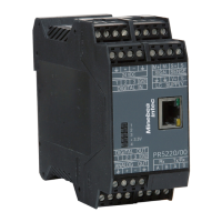
Installing the Instrument
PR 5220 Instrument Manual
EN-28 Sartorius
3.1.6 Load Cell Connection
The cable colors shown in this chapter are applicable to the Sartorius PR 62XX series load cells.
Before connecting other types, carefully follow the information related to the assignment of
load cell/platform cable colors.
• The distance between the measuring cables and the power cables should be at least 1 m.
• The measuring cables should be laid in separate cable conduits or steel pipes connected to earth potential.
• Power cables should be crossed at right angles.
Load cell supply circuit
The load cell supply voltage is fixed to 12 V DC and protected against short circuit.
Load resistance of load cells ≥75 ¥, e.g. 8 load cells of 650 ¥ each.
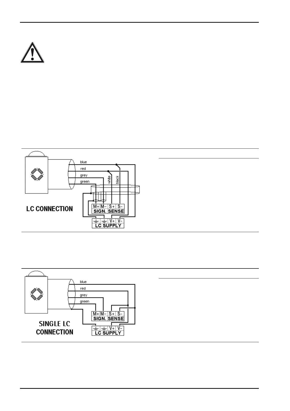
3.1.6.1 Connection Using 6-Wire Technology
See also label on the housing outside (Chapter 2.3) and manual of the junction box.
Terminal Description
SIGN. M+
SIGN. M-
SENSE S+
SENSE S-
LC SUPPLY V+
LC SUPPLY V-
+ signal/LC output
- signal/LC output
+ sense
- sense
+ supply/excitation
- supply/excitation
3.1.6.2 Connection of a Load Cell in 4-Wire Technology
Note that links between SENSE S+ and LC SUPPLY V+ and between SENSE S- and LC SUPPLY V- directly at the
transmitter must be provided.
Terminal Description
SIGN. M+
SIGN. M-
SENSE S+
SENSE S-
LC SUPPLY V+
LC SUPPLY V-
+ signal/LC output
- signal/LC output
+ sense
- sense
+ supply/excitation
- supply/excitation
3.1.6.3 Connecting PR 6221 Load Cells
See installation manual PR 6221 and PR 6021/08, -/68.
 Loading...