SLT12 User Manual
198
point.
4. Rotate the illumination part, every 90°, and observe the center mark of the alignment point
and the overlap of the cross.
5. If the center mark of the optical aligner is always coincident with the cross when the
alignment section is rotated, no correction is necessary. Otherwise, it should be corrected
according to the following method.
17.7.2 Adjust
1. Remove the corrective screw cover between the optical aligner eyepiece and the focusing
handwheel.
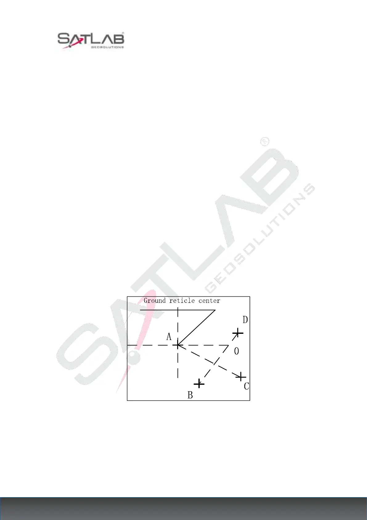
2. Fix the crossed white paper and mark on the paper the center mark the fall point of the
aligner for every 90° rotation of the instrument, such as points A, B, C, and D in the figure.
3. Connect the diagonal points AC and BD with a straight line, and the intersection of the two
lines is O.
4. Adjust the four alignment screws of the aligner with the alignment pin so that the center
mark of the aligner coincides with the O point.
Figure 17- 7
5. Repeat inspection step 4 and check the calibration until it meets the requirements.
6. For the laser under the point, then unscrew the laser cover, use 1 # hexagonal wrench to
adjust the three screws, while tightening and loosening, and finally adjust the laser spot to 0