SLT12 User Manual
197
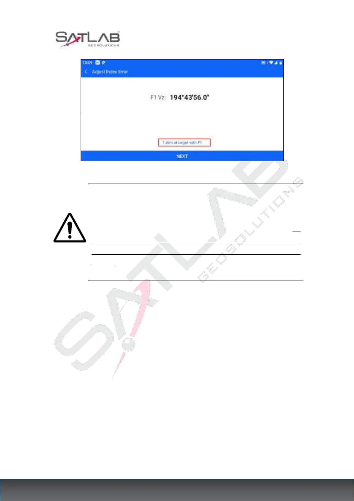
Figure 17- 6
Note: 1. Repeat the test steps to re-measure the indicator difference (i angle).
If the indicator difference still does not meet the requirements, you should
check whether the step operation of the correction indicator zero setting (the
vertical angle shown in the zero setting process is the value without
compensation and correction, only for reference in the setting and not for other
purposes) is wrong, and whether the target illumination is accurate, etc., and
then set it again as required.
6. After repeated operations still does not meet the requirements, should be sent to the factory
for maintenance.
17.7 Laser Plummet
17.7.1 Check
1. Place the instrument on a tripod, draw a cross on a piece of white paper, and place it on the
ground directly below the instrument.
2. After adjusting the focus of the aligner (for optical aligner) or opening the laser aligner,
move the white paper so that the cross is located in the center of the field of view (or laser
spot).
3. Turn the foot spiral so that the center mark of the aligner coincides with the crossover