SLT12 User Manual
70
8.1.5 CAD Stakeout Tool
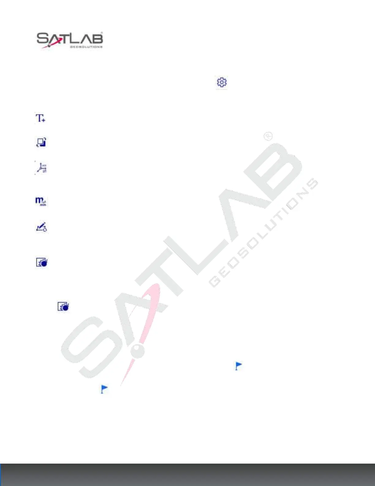
When you enter the CAD Stakeout interface, click on the Settings button in the right toolbar to expand the
CAD module's related tools.
Font size: You can modify the dot name size of the acquisition points in the CAD stakeout interface.
Toggle Base Map: You can toggle the base map to black/white.
Switch coordinate system: Click this button to switch between displaying the user coordinate system or the
world coordinate system.
Conversion of base map source length units: You can convert the base map source length units to m or mm.
Redraw: When the interface is enlarged, there may be a phenomenon that the arc is not drawn smoothly,
click Redraw to refresh it to make it draw correctly.
Blow up the entity: you can blow up the selected feature into multiple entities. The operation method is.
1. After loading the CAD file, click on the graphical interface to select the block or polyline.
2. Click , the selected block can be blown up into multiple independent entities.
8.1.6 Line stakeout
1. Import the CAD files that need to be stakeout
2. Click to select the target line to be stakeout, and display the "stakeout " button.
3. Click the "stakeout" button to enter the stakeout parameter setting interface, you can set the stakeout
parameters such as left/right offset, front/back offset, front/back offset increment, top/bottom offset, etc.