G.7
Date Code 20080918 Instruction Manual SEL-749M Relay
Relay Word Bits
Definitions
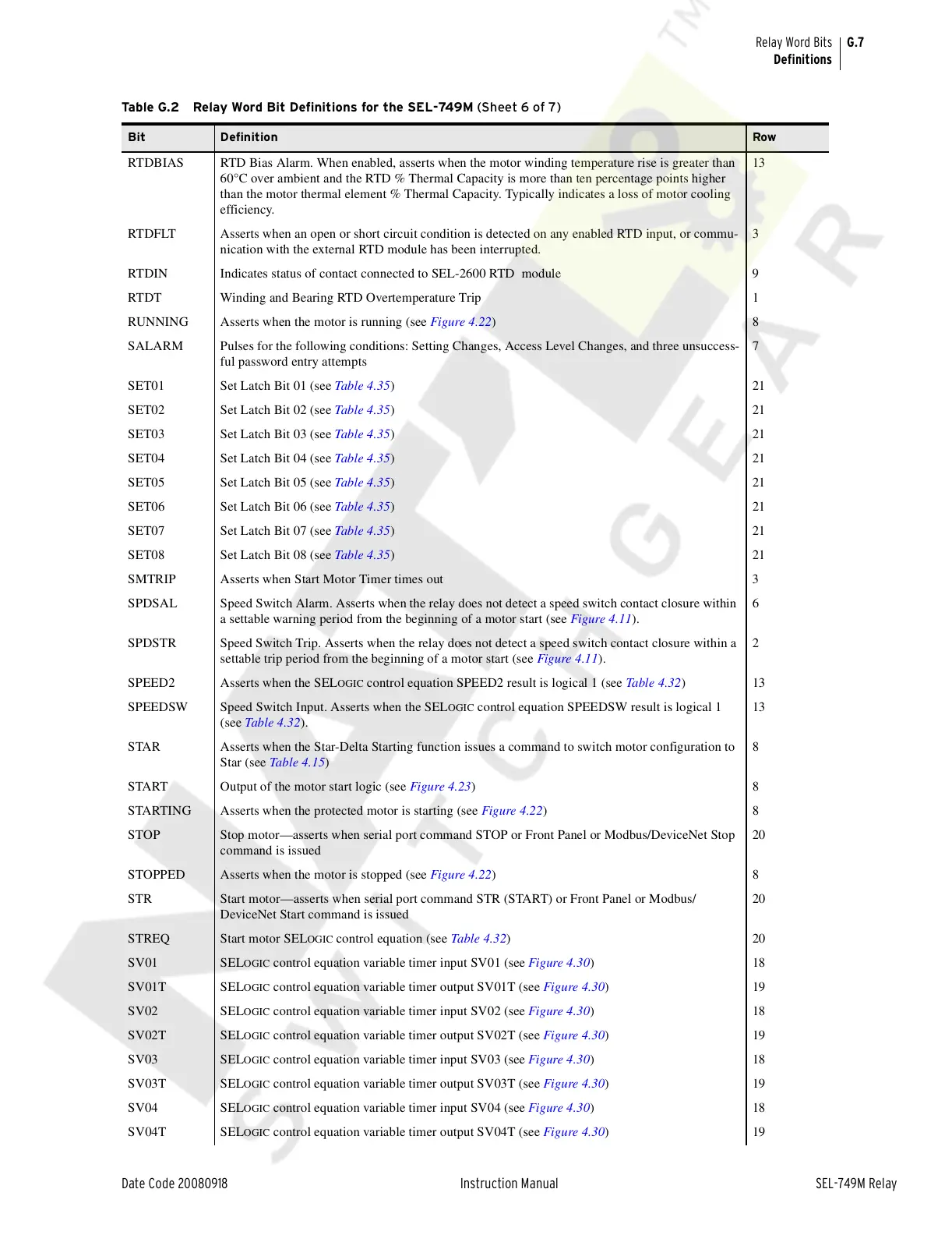
RTDBIAS RTD Bias Alarm. When enabled, asserts when the motor winding temperature rise is greater than
60°C over ambient and the RTD % Thermal Capacity is more than ten percentage points higher
than the motor thermal element % Thermal Capacity. Typically indicates a loss of motor cooling
efficiency.
13
RTDFLT Asserts when an open or short circuit condition is detected on any enabled RTD input, or commu-
nication with the external RTD module has been interrupted.
3
RTDIN Indicates status of contact connected to SEL-2600 RTD module 9
RTDT Winding and Bearing RTD Overtemperature Trip 1
RUNNING Asserts when the motor is running (see Figure 4.22)8
SALARM Pulses for the following conditions: Setting Changes, Access Level Changes, and three unsuccess-
ful password entry attempts
7
SET01 Set Latch Bit 01 (see Table 4.35)21
SET02 Set Latch Bit 02 (see Table 4.35)21
SET03 Set Latch Bit 03 (see Table 4.35)21
SET04 Set Latch Bit 04 (see Table 4.35)21
SET05 Set Latch Bit 05 (see Table 4.35)21
SET06 Set Latch Bit 06 (see Table 4.35)21
SET07 Set Latch Bit 07 (see Table 4.35)21
SET08 Set Latch Bit 08 (see Table 4.35)21
SMTRIP Asserts when Start Motor Timer times out 3
SPDSAL Speed Switch Alarm. Asserts when the relay does not detect a speed switch contact closure within
a settable warning period from the beginning of a motor start (see Figure 4.11).
6
SPDSTR Speed Switch Trip. Asserts when the relay does not detect a speed switch contact closure within a
settable trip period from the beginning of a motor start (see Figure 4.11).
2
SPEED2 Asserts when the SEL
OGIC control equation SPEED2 result is logical 1 (see Table 4.3 2)13
SPEEDSW Speed Switch Input. Asserts when the SEL
OGIC control equation SPEEDSW result is logical 1
(see Table 4.32).
13
STAR Asserts when the Star-Delta Starting function issues a command to switch motor configuration to
Star (see Table 4.15)
8
START Output of the motor start logic (see Figure 4.23)8
STARTING Asserts when the protected motor is starting (see Figure 4.22)8
STOP Stop motor—asserts when serial port command STOP or Front Panel or Modbus/DeviceNet Stop
command is issued
20
STOPPED Asserts when the motor is stopped (see Figure 4.22)8
STR Start motor—asserts when serial port command STR (START) or Front Panel or Modbus/
DeviceNet Start command is issued
20
STREQ Start motor SEL
OGIC control equation (see Table 4.32)20
SV01 SEL
OGIC control equation variable timer input SV01 (see Figure 4.30)18
SV01T SEL
OGIC control equation variable timer output SV01T (see Figure 4.30)19
SV02 SEL
OGIC control equation variable timer input SV02 (see Figure 4.30)18
SV02T SEL
OGIC control equation variable timer output SV02T (see Figure 4.30)19
SV03 SEL
OGIC control equation variable timer input SV03 (see Figure 4.30)18
SV03T SEL
OGIC control equation variable timer output SV03T (see Figure 4.30)19
SV04 SEL
OGIC control equation variable timer input SV04 (see Figure 4.30)18
SV04T SEL
OGIC control equation variable timer output SV04T (see Figure 4.30)19
Table G.2 Relay Word Bit Definitions for the SEL-749M (Sheet 6 of 7)
Bit Definition Row
Courtesy of NationalSwitchgear.com