G.8
SEL-749M Relay Instruction Manual Date Code 20080918
Relay Word Bits
Definitions
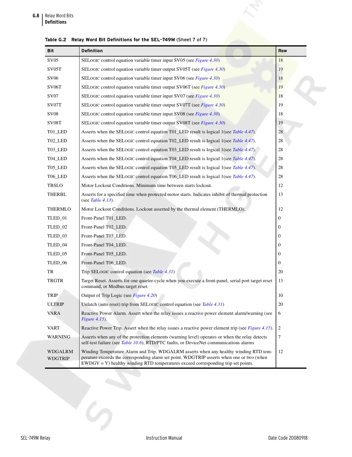
SV05 SELOGIC control equation variable timer input SV05 (see Figure 4.30)18
SV05T SEL
OGIC control equation variable timer output SV05T (see Figure 4.30)19
SV06 SEL
OGIC control equation variable timer input SV06 (see Figure 4.30)18
SV06T SEL
OGIC control equation variable timer output SV06T (see Figure 4.30)19
SV07 SEL
OGIC control equation variable timer input SV07 (see Figure 4.30)18
SV07T SEL
OGIC control equation variable timer output SV07T (see Figure 4.30)19
SV08 SEL
OGIC control equation variable timer input SV08 (see Figure 4.30)18
SV08T SEL
OGIC control equation variable timer output SV08T (see Figure 4.30)19
T01_LED Asserts when the SEL
OGIC control equation T01_LED result is logical 1(see Table 4.47). 28
T02_LED Asserts when the SEL
OGIC control equation T02_LED result is logical 1(see Table 4.47). 28
T03_LED Asserts when the SEL
OGIC control equation T03_LED result is logical 1(see Table 4.47). 28
T04_LED Asserts when the SEL
OGIC control equation T04_LED result is logical 1(see Table 4.47). 28
T05_LED Asserts when the SEL
OGIC control equation T05_LED result is logical 1(see Table 4.47). 28
T06_LED Asserts when the SEL
OGIC control equation T06_LED result is logical 1(see Table 4.47). 28
TBSLO Motor Lockout Conditions. Minimum time between starts lockout. 12
THERBL Asserts for a specified time when protected motor starts. Indicates inhibit of thermal protection
(see Table 4.13).
13
THERMLO Motor Lockout Conditions. Lockout asserted by the thermal element (THERMLO). 12
TLED_01 Front-Panel T01_LED. 0
TLED_02 Front-Panel T02_LED. 0
TLED_03 Front-Panel T03_LED. 0
TLED_04 Front-Panel T04_LED. 0
TLED_05 Front-Panel T05_LED. 0
TLED_06 Front-Panel T06_LED. 0
TR Trip SEL
OGIC control equation (see Table 4.31)20
TRGTR Target Reset. Asserts for one quarter-cycle when you execute a front-panel, serial port target reset
command, or Modbus target reset.
13
TRIP Output of Trip Logic (see Figure 4.20)10
ULTRIP Unlatch (auto reset) trip from SEL
OGIC control equation (see Table 4.31)20
VARA Reactive Power Alarm. Assert when the relay issues a reactive power element alarm/warning (see
Figure 4.15).
6
VART Reactive Power Trip. Assert when the relay issues a reactive power element trip (see Figure 4.15). 2
WARNING Asserts when any of the protection elements (warning level) operates or when the relay detects
self-test failure (see Table 10.6), RTD/PTC faults, or DeviceNet communications alarms
7
WDGALRM
WDGTRIP
Winding Temperature Alarm and Trip. WDGALRM asserts when any healthy winding RTD tem-
perature exceeds the corresponding alarm set point. WDGTRIP asserts when one or two (when
EWDGV = Y) healthy winding RTD temperatures exceed corresponding trip set points.
12
Table G.2 Relay Word Bit Definitions for the SEL-749M (Sheet 7 of 7)
Bit Definition Row
Courtesy of NationalSwitchgear.com