32
Manual – MOVIDRIVE® MDX61B Safety Module Option MOVISAFE® DCS..B
4
Unit structure of DCS21B/22B
Unit Structure
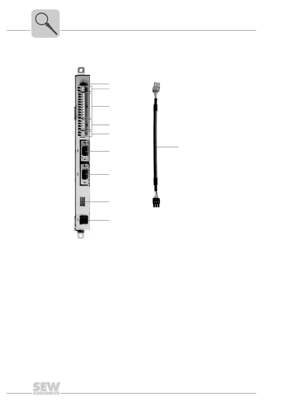
4.4 Unit structure of DCS21B/22B
1971124363
[1] Status LEDs
[2] X80: Terminal for DC 24 V voltage supply
[3] X81: Terminal for digital inputs DI1 - DI8 and pulse signals P1, P2
[4] X82: Terminal for digital outputs DO0 / DO1
[5] X83: Terminal for digital output DO2
[6] X84: Socket for HTL/TTL incremental, SIN/COS or SSI absolute encoder
[7] X85: Socket for HTL/TTL incremental, SIN/COS or SSI absolute encoder
[8] X86: Socket for CAN interface
[9] X87: Socket for parameter setting and diagnostic interface
[10] Prefabricated cable DAE34B (part number: 1821 307 3) for CAN bus connection
between DCS21B/22B X86 and X31 of the DFS12B/DFS22B option.
[1]
[2]
[3]
[4]
[5]
[6]
[7]
[9]
[8]
X86
DCS21B
[10]
 Loading...