Manual – MOVIDRIVE® MDX61B Safety Module Option MOVISAFE® DCS..B
77
6
Operating states
Startup
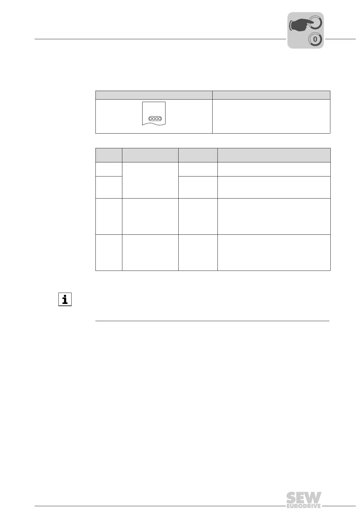
6.5 Operating states
After each restart of the DCS..B option, the following operating states are run through
and are displayed at the front status LEDs in fault-free operation.
6.6 Configuring the measuring sections
The most important input parameters for the monitoring functions of the DCS..B option
are:
• Position
•Velocity
• Acceleration
These input parameters are generated in a dual-channel from the connected encoder
systems. To achieve performance level e according to EN ISO 13849-1, always two
independent encoder systems are required. To achieve performance level d according
to EN ISO 13849-1, one encoder system can be sufficient for certain applications.
DCS..B Status LEDs
1991483403
• LED F: Alarm/error
• LED WD: Watchdog
• LED B: System B
• LED A: System A
Operat-
ing state
LED display Mode Description
1 • LEDs "A" and "B"
flash in sync
(change every
1.2 s)
•LED "WD" off
•LED "F" off
STARTUP Synchronization between both processor systems
and check of the configuration/firmware data.
2 SEND CONFIG Distribution of the configuration/firmware data and
another check of this data. Range check of the
configuration data.
3 • LEDs "A" and "B"
flash in sync
(change every
0.8 s)
•LED "WD" off
•LED "F" off
STARTUP BUS Only with DCS21B/22B option. The option waits
until the safety controller re-integrates the option.
4 • LEDs "A" and "B"
flash in sync
(change every
0.4 s)
•LED "WD" on
•LED "F" off
RUN Watchdog is active, i.e. all outputs can be
switched.
DCS21B
F
WD
B
A
INFORMATION
In operating states 1, 2 and 3, the outputs are automatically switched off by the firm-
ware. In "RUN" mode (operating state "4"), the outputs are controlled by the imple-
mented MOVISAFE
®
program or the program in the higher-level controller.
 Loading...