52
Manual – MOVIDRIVE® MDX61B Safety Module Option MOVISAFE® DCS..B
5
Connecting digital outputs
Installation
5.9 Connecting digital outputs
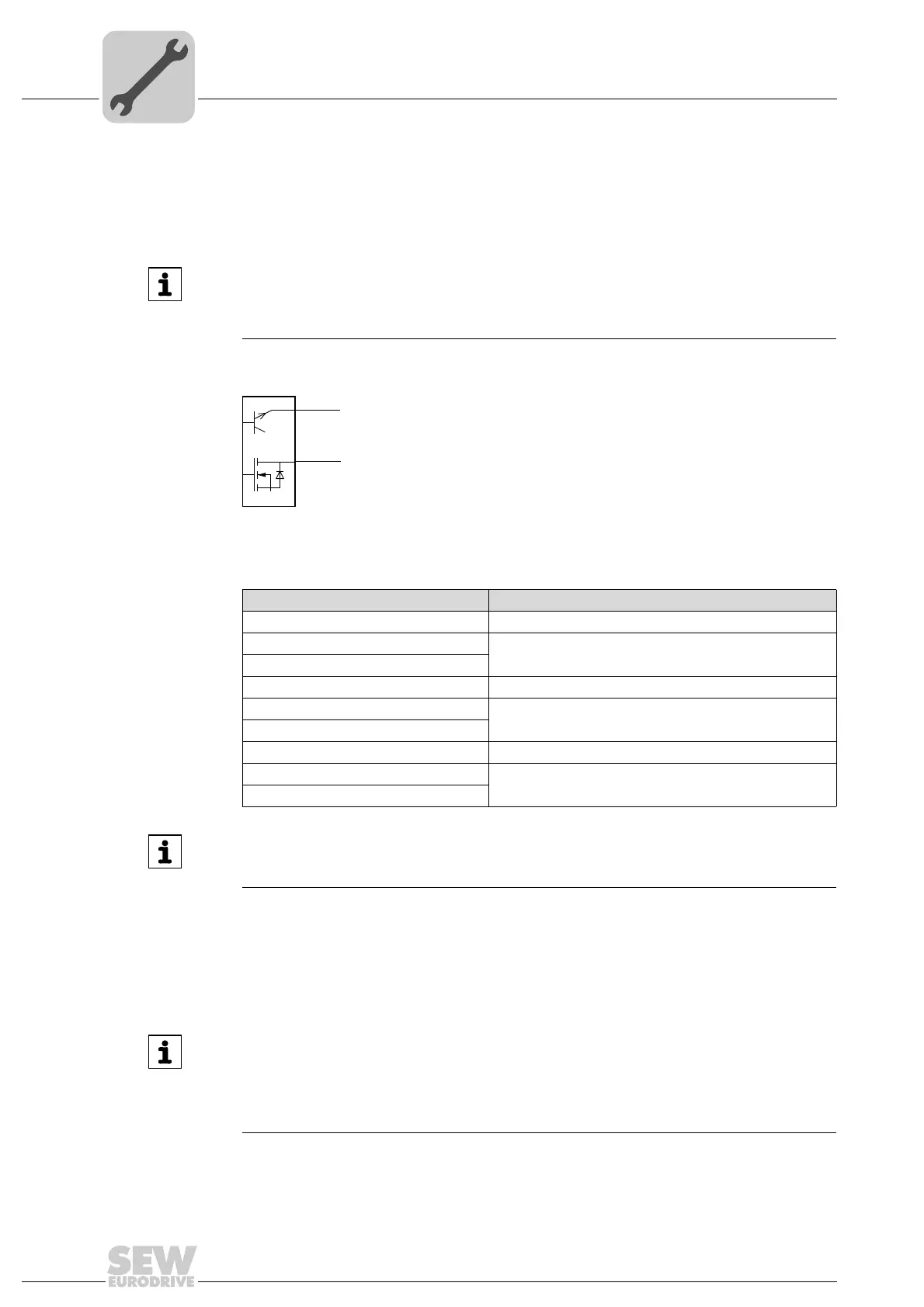
Option DCS..B offers a total of 6 digital outputs. The 3 digital outputs DO0_P, DO1_P
and DO2_P are positive switching, the 3 digital outputs DO0_M, DO1_M and DO2_M
are negative switching.
Depending on the required performance level, you can use digital outputs individually or
combined in groups.
If the unit-internal diagnostic function is enabled, it will cyclically check the digital outputs
for proper functioning. During this plausibility check, the digital output is switched to its
inverse value for the duration of the check (< 500 μs). This means a P digital output is
briefly switched to DC 0 V potential, and an M digital output is briefly switched to
DC 24 V potential. If an error is detected, the DCS..B option switches to alarm/error
state and indicates this state (see chapter "Diagnostics").
INFORMATION
The following sample circuits assume that the switching elements are configured in
accordance with the required performance level to EN ISO 13849-1 and that safety
approval has been granted for the application in question.
2060216459
Digital output Remark
DO0_P and DO0_M Up to performance level e
DO0_P
Only functional
DO0_M
DO1_P and DO1_M Up to performance level e
DO1_P
Only functional
DO1_M
DO2_P and DO2_M Up to performance level e
DO2_P
Only functional
DO2_M
DCS 21B/31B
X83
1
2
DO2_P
DO2_M
INFORMATION
Only the combination of P and M switching output may be used for safety-related
applications.
INFORMATION
The digital outputs of option DCS..B must not be connected to fast touch probe inputs
because the diagnostic function might lead to unintentional switching operations.
These are, for example, digital inputs DI00 (X13:1, fixed assignment with "/Controller
inhibit"), DI02 (X13:3) and DI03 (X13:4) of MOVIDRIVE
®
B.
 Loading...