Manual – MOVIDRIVE® MDX61B Safety Module Option MOVISAFE® DCS..B
59
5
Connecting digital outputs
Installation
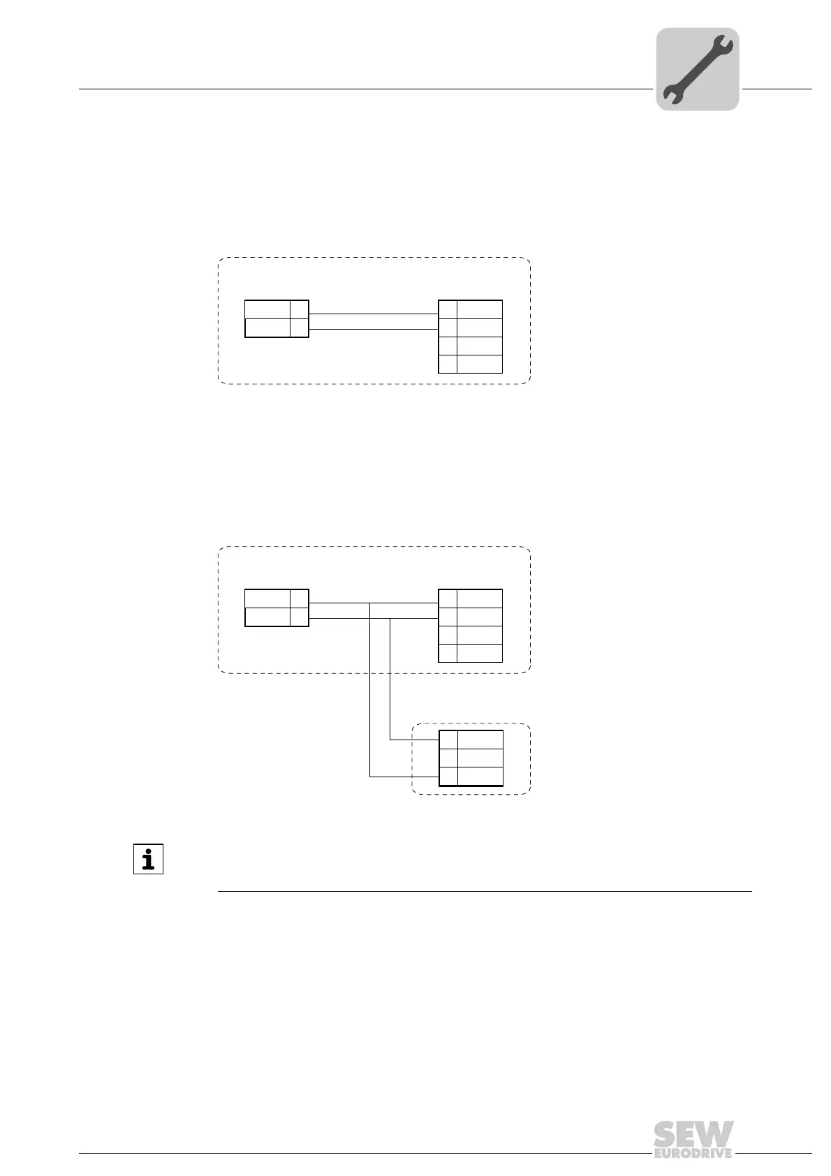
5.9.3 Using digital outputs for switching safe stop with MOVIDRIVE
®
B
Digital outputs DO2_P and DO2_M can be used to control the safe stop function (X17)
of MOVIDRIVE
®
B.
The following wiring diagram shows the wiring of MOVIDRIVE
®
B with installed DCS..B
option and safety-relevant BST brake module. For more detailed information about the
BST option, refer to the document "Safety-Relevant BST Brake Module for Control
Cabinet Installation".
9007201314961163
9007201315509771
MOVIDRIVE
®
MDX61B
DGND
DO2_P
VO24
SOV24
SVI24
1
2
3
4
X17
X83
DCS 21B/22B/31B/32B
1
DO2_M
2
MOVIDRIVE
®
MDX61B
DGND
DO2_P
VO24
SOV24
SVI24
1
2
3
4
X17
X83
DCS 21B/22B/31B/32B
1
DO2_M
2
N.C.
S0V24
SVI24
5
6
BST
●
●
INFORMATION
Output X83 of the DCS..B option can drive a maximum of two MOVIDRIVE
®
B units
and two safety-related BST brake modules irrespective of the required current.
 Loading...