44
Manual – MOVIDRIVE® MDX61B Safety Module Option MOVISAFE® DCS..B
5
Connecting digital inputs DI1 to DI8
Installation
5.8 Connecting digital inputs DI1 to DI8
Option DCS..B is equipped with 8 digital inputs (DI1 – DI8). They are suitable for
connecting single or dual-channel sensors with or without pulsing.
The connected signals must have a "High" level of DC 24 V (DC +15 V to DC +30 V)
and a "Low" level of DC 0 V (DC -3 V to DC +5 V). The inputs are equipped with input
filters.
The unit-internal pulse voltages can be used to detect a cross fault in the connected sig-
nal lines. They can be connected with the digital inputs as described in chapter "Using
pulse outputs P1 and P2".
No sensors with self-monitoring output (OSSD) can be connected to the digital inputs of
option DCS..B.
In all operating states, an integrated diagnostic function cyclically tests whether the
digital inputs and input filters are functioning properly. If a fault is detected, the DCS..B
option switches to alarm status and indicates this status (see chapter "Diagnostics").
Depending on the required performance level, you can use digital inputs individually or
combined in groups. The MOVISAFE
®
Config software interface provides various, pre-
defined input elements for this purpose (see chapter "Description of input elements").
The DCS..B option has separate signal processing paths for every safety input (DI1 –
DI8).
INFORMATION
The following sample circuits assume that the switching elements are configured in
accordance with the required performance level to EN ISO 13849-1 and that safety
approval has been granted for the application in question.
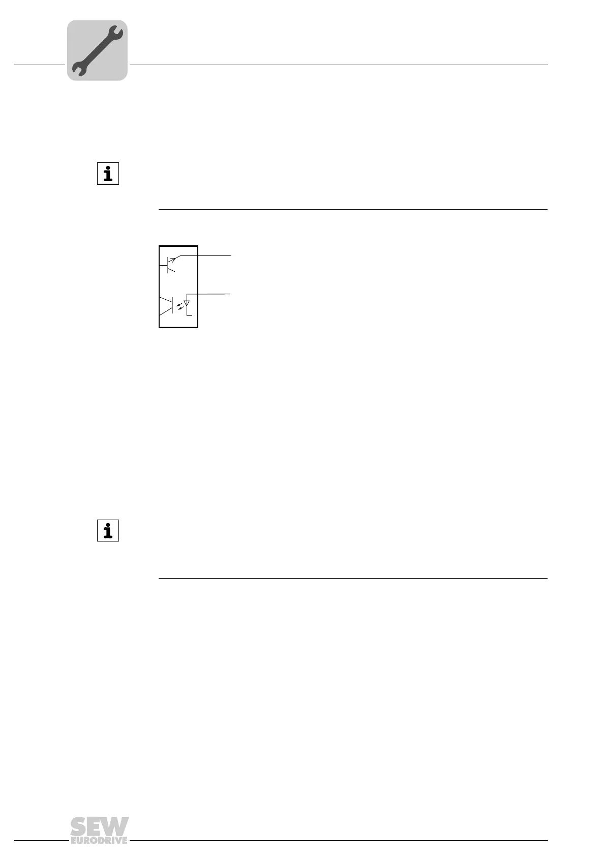
2408460299
DCS 21B/31B
X81
1 P1
2 DI1
INFORMATION
You must configure the digital input DI6 of the DCS31B/32B option as reset
input to be able to acknowledge any triggered safety function or alarm and error
message. For the DCS21B/22B option, you must send an acknowledgement via the
safe fieldbus (PROFIsafe).
 Loading...