5.2.9.2 Pin assignment FX3-EBX3
C1 encoder connection
T
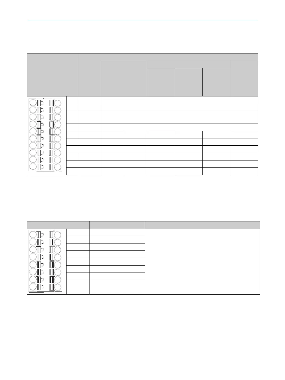
able 31: Encoder connection C1, FX3-EBX3
Terminal Designa‐
t
ion
Wiring
Sine/Cosine encoder A/B incremental encoder SSI encoder
2output
pairs
(HTL24V,
HTL12V,
TTL)
2outputs
(HTL24V,
HTL12V,
TTL)
2 pairs of
outputs
(RS-422)
1)
1 NC2 Not connected to the FX3-EBX3
2)
2 NC1 Not connected to the FX3-EBX3
2)
3 U
out
Encoder voltage supply from the on-board voltage supply of this FX3-EBX3, switcha‐
ble be
tween 5V, 7V, 12V and 24V nominal
4 ENCx_0V
3)
GND connection for encoder
5 ENCx_C-
3)
– – – – B– Clock -
6 ENCx_C+
3)
– – – – B+ Clock+
7 ENCx_B-
3)
Sin– Sin_Ref B– GND – –
8 ENCx_B+
3)
Sin+ Sin B+ B – –
9 ENCx_A-
3)
Cos– Cos_Ref A– GND A– Data–
10 ENCx_A+
3)
Cos+ Cos A+ A A+ Data+
1)
Only for encoder 1, i.e. if it is the first encoder/motor feedback connection unit.
2)
Used to forward a signal, e.g. for an external voltage supply (instead of using U
out
).
3)
x = 1 if it is the first encoder/motor feedback connection unit, i.e. if plug connector C3 is directly connected to the FX3-MOCx.
x = 2 if it is t
he second encoder/motor feedback connection unit, i.e. if plug connector C3 is connected to another encoder/motor feedback
connection unit.
C2
T
able 32: C2 terminal, FX3-EBX3
Terminal Designation Description
1 NC Not connected to the FX3-EBX3, only used to forward signals
2 NC
3 NC
4 NC
5 NC
6 NC
7 NC
8 NC
ELECTRICAL INSTALLATION 5
8012478/1IG6/2023-02-24 | SICK O P E R A T I N G I N S T R U C T I O N S | Flexi Soft Modular Safety Controller
65
Subject to change without notice