Maintenance and meter exchange
FLOWSIC500 · Operating Instructions · 8025733/1GMJ/V4-2/2022-07 · © SICK Engineering GmbH 119
Subject to change without notice
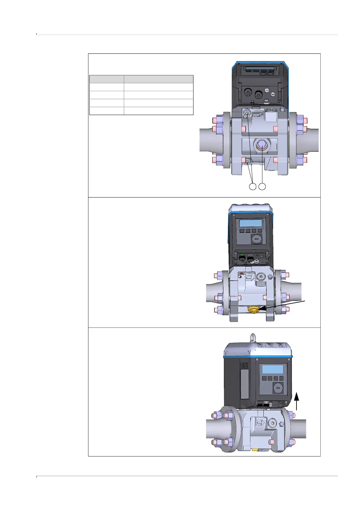
3 Remove securing screws (1) with the
Allen key
4 Loosen center bolt (2) five to six
turns.
5 Instead of the closure cap, at first
manually screw the test cap for the
respective meter size in until the test
cap touches the center bolt.
6 Keep on screwing the test cap in with
the socket wrench against the
resistance of the center bolt until the
test cap is completely screwed in.
The center bolt pushes the seals
upwards and lifts the gas flow meter
up.
1 2
Meter size Number of securing screws
DN50/2" 2
DN80/3" 3
DN100/4" 4
DN150/6" 4
approx. 5
mm