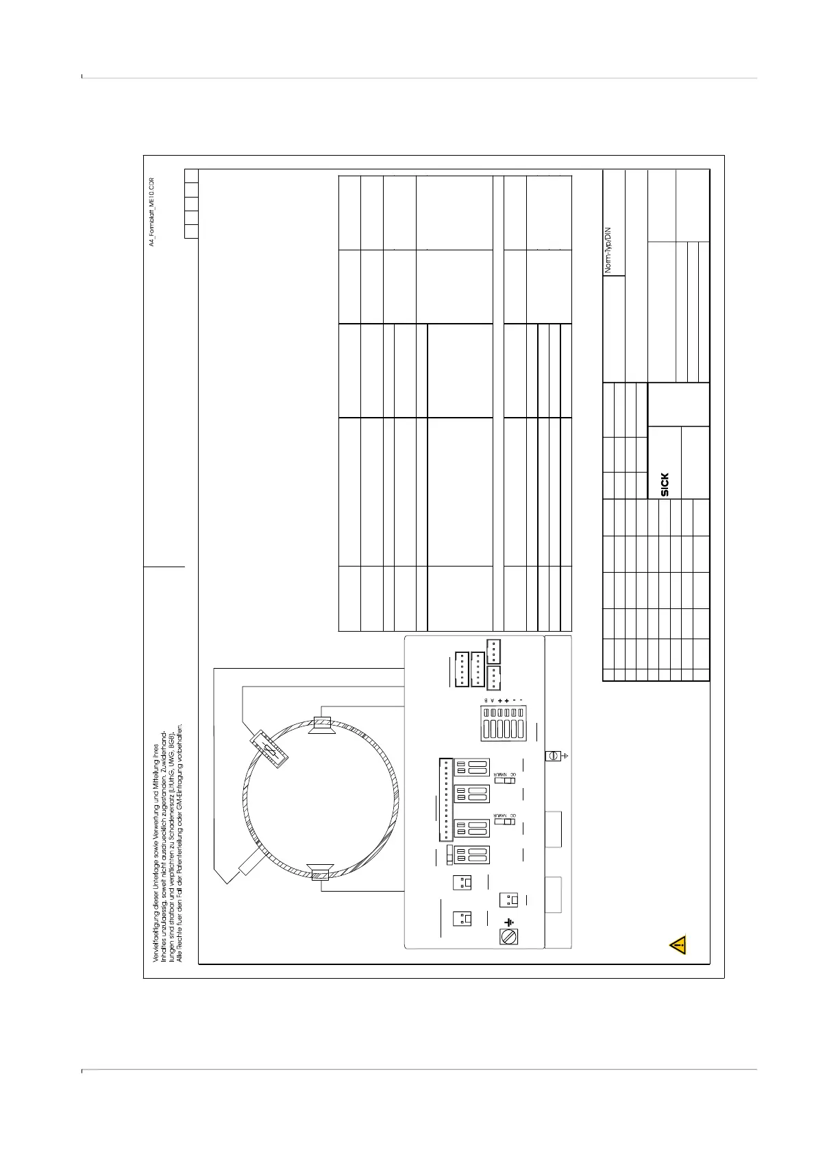
Fig. 85 Control diagram 9215965 (page 6)
SICK Engineering GmbH
Bergener Ring 27
01458 Ottendorf-Okrilla
Verteildatum:
Page
Ersatz für:
Änderung
gez.
Tag
Name
Ind.
Tag Name
Maßstab:
Werkstoff
Ersetzt durch:
Gepr.
Ursprung:
MKO
6of7
2014-07-16
Connector. Function / signal Internal connection Operating
parameters
Safety
parameters*)
M12 , male,
B-coded
Pin 1 ext. power supply “–” (GND) “ BAT1 –“ terminal nominal
input voltage
4.5…16 V
Ui = 20 V
Ii = 667 mA
Pi = 772 mW
Pin 2 ext. po wer supply “+” “BAT1 +” terminal
Pin 3 Dig ital output DO1 “–“ (GND) “DO1 –“ terminal
passive,
non-isolated,
Low side switch
max.16 V
nom. 20 mA
Ron < 110 Ohm
Roff >1 MOhm
Ui = 20 V
Pi = 1.1 W
Uo = 8.2 V
Io = 0.83 mA
Po = 1.7 mW
Co = 7.6 μF
Lo = 100 mH
Pin 4 Digital output DO1 “ +“ “DO1 +” terminal
M12, male,
A-coded
Configuration
“RS485 external powered”
optically isolated
Pin 1 Auxiliary power supply input “+” “RS485 +” terminal nominal
input voltage
2.7... 5 V
(LV)
4…16V
Ui = 20 V
Pi = 1.1 W
Ci = 1.35 μF
Li = 0.03 mH
Pin 2 “RS485_ Data Interface “A” “RS485 A” terminal
Pin 3 Auxiliary power supply input “–“ “RS485 –” terminal
Pin 4 RS485_ Data Int er face “B” “RS485 B“ terminal
Preselected Configuration for circular connectors M12, male
Configuration “RS485 external powered”
*) values apply for the interconnection of all circuits within each connector
Optionally Exia
Temperature Sensor
Optionally Exia
pressure sensor
Ultrasonic Transducers
Temperature range
and pressure range
see Marking plate
Class I, Division 1, Groups C and D, Temp. Code T4
Ex ia IIB T4 Ga
ClassI,Zone0AExiaIIBT4Ga
.
-25°C < Tamb < 60°C
,
for extended range see Marking plate
.
In the US install in accordance with the NEC (NFPA70, Article 504)
and ANSI/ISA-RP12.06.01
In Canada install in accordance with CEC part 1
Exia Intrinsically Safe; Securite Intrinseque
9215965
M12
ext. Power + DO1
RS485
M12
Wire size for all terminals: 0,14..0, 5 mm (AWG 24 ... 20)
2
4mm
(AWG 12)
2
EXT. POWER
BAT1
n.c.
DO3
DO0
+-
RS485
P1
P2
T1
T2
SENSORS
DISPLAY
LOCK
OFF ON
5..12V
NAMUR
4,5..16V
1.5 mm²
(AWG 16)
:
R:100
S
2..16V
2..16V
DO2
2..16V
DO1
+-
BAT2
+-
+- +- +-
kochami
draft
01
2014-08-27
gepr.
kochami
2014-08-27
Control drawing FLOWSIC500 isolated I/O
kochami
Ed.6
02
WARNING: EXPLOSION HAZARD
Substitution of components may impair Intrinsic safety
AVERTISSEMENT: La substituti on
de composants peut compromettre la securite intrinseque.
RISQUE D` EXPLOSION -
2015-09-24
kochami
ZY57
03
2018-05-02