28 FLOWSIC500 · Operating Instructions · 8025733/1GMJ/V4-2/2022-07 · © SICK Engineering GmbH
Product description
Subject to change without notice
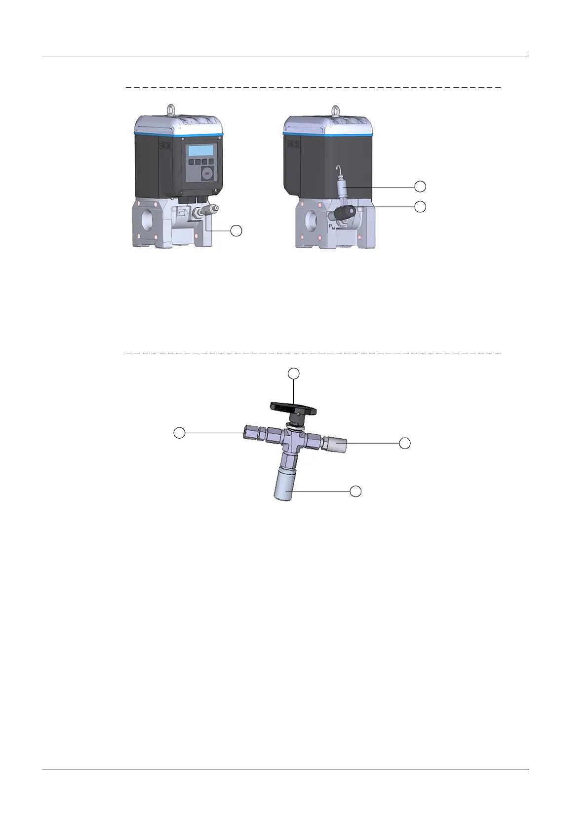
Fig. 5 FLOWSIC500 with external sensors and test valve BDA04
A three-way test valve (→ Fig. 6) that is fitted next to the FLOWSIC500 is used for gas
temperatures to -40°C.
Fig. 6 Three-way test valve with p-sensor and Minimess coupling
1 Pressure sensor
2 Test valve BDA04
3 Temperature sensor
2
3
1
1
2
3
4
1 Pipe screw fitting 1/4“ NPT on pipe D06
or pipe screw fitting 1/4“ NPT on pipe 1/4“
2 Hand lever
3 Test connection (Minimess coupling)
4 Pressure sensor, connection thread G 1/4“