66 FLOWSIC500 · Operating Instructions · 8025733/1GMJ/V4-2/2022-07 · © SICK Engineering GmbH
Installation
Subject to change without notice
Tools required
● Allen keys SW 3 and 2.5
● Jaw wrench SW 6
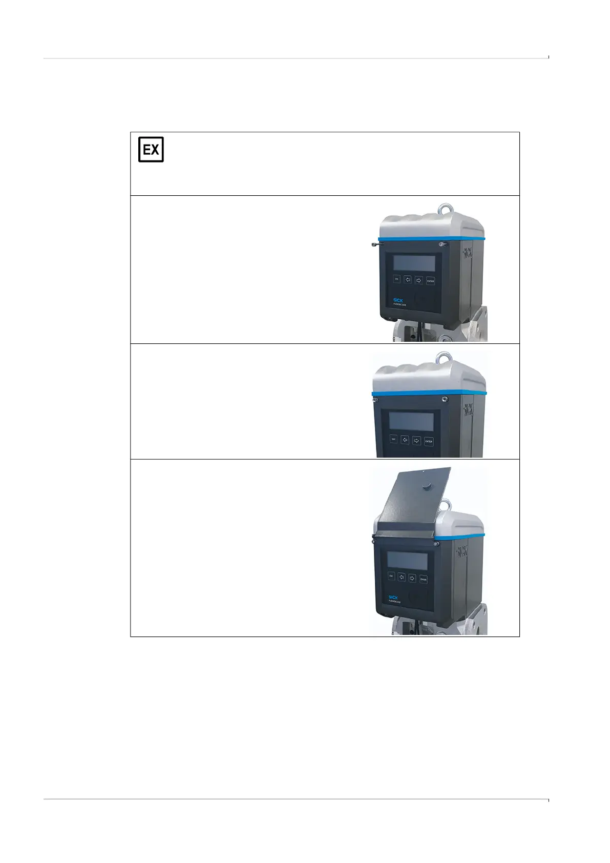
The Ex i terminal compartment of the
FLOWSIC500 can be accessed after the electronics cover has been opened.
The cover may also be opened in the hazardous area when under voltage.
However, safe separation between the various intrinsically safe power circuits
must not be breached.
1 Loosen and unscrew the two upper screws
of the electronics cover with an Allen key
SW 3.
2 Instead, mount the delivered screws with a
SW 6 jaw wrench.
3 Mount the display cover with the pre-
mounted screws (captive) using an Allen key
SW 2.5.