100
8024638/AE00/V1-0/2019-09| SICKSERVICE MANUAL | MCS200HW
Subject to change without notice
5 REPAIRS
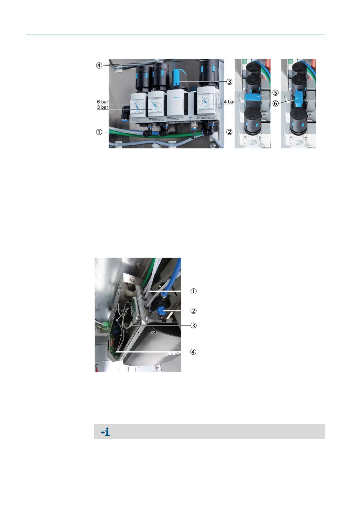
Fig. 147: Pressure reducer unit
3 Close the blue ball valve (see Fig. 148 “Pressure control module, hose connections”,
page 100).
4 Remove the electronics housing cover see Chapter “Removing the electronics housing
cover”, page 88.
5 Disconnect all hose connections from the slots.
.
Fig. 148: Pressure control module, hose connections
1 Inlet of instrument air with zero gas quality
2 Inlet of instrument air solely as induction air for ejector
3 Manual valve for instrument air selection
43 pressure reducers (adjustable)
5Manual valve (closed)
6Manual valve (open)
1 Hose connections
2Ball valve
3 Pressure control module, hose connection
3 Pressure control module, plug connection
To disconnect the hoses, press the metal ring down, then pull the hose off.

 Loading...

