126
8024638/AE00/V1-0/2019-09| SICKSERVICE MANUAL | MCS200HW
Subject to change without notice
5 REPAIRS
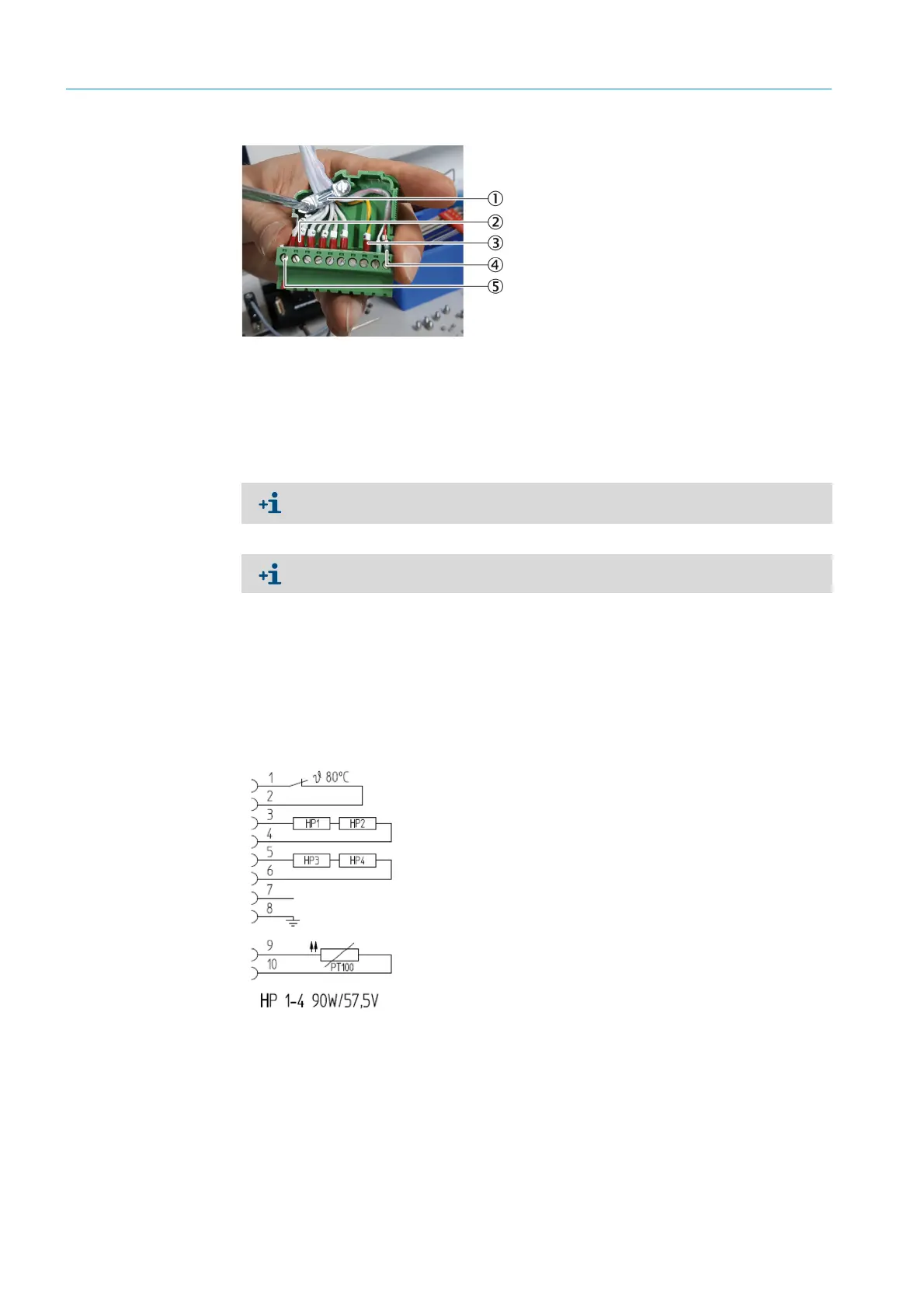
Fig. 196: Contact plug, assignment (example)
2 Loosen the clamping screws of the cables for the PT100.
3 Pull the PT100 cable out of the cable conduit.
5 Plug in the new PT100.
6 Connect the new PT100 to the heating garland:
1 Guide the cable of the new PT100 through the cable conduit to the plug.
2 Fasten the cable of the new PT100 with clamping screws in the contact plug accord-
ing to the circuit diagram (see Fig. 197 “Circuit diagram, PT100, sender/receiver
unit”, page 126).
▸ Shorten the cables to the appropriate length.
Fig. 197: Circuit diagram, PT100, sender/receiver unit
3 Fasten the fastening clip in the contact plug.
4 Close the contact plug.
7 Screw the fastening clip of the cable conduit tight.
8 Attach the sheet metal covers and fit the sender/receiver unit (see Chapter “Fitting the
complete sender/receiver unit”, page 98).
9 Fit the cell (see Chapter “Fitting the complete cell”, page 18).
1Fastening clip
2 Leads for thermostatic switches (2) and heating cartridges (4)
3Grounding
4PT100
5Clamping screw
The cable leads are numbered consecutively. Note the assignment of the clamping
screws for reconnection. E.g. with a photo or use the circuit diagram.
Heating cartridge pairs have the clamps next to each other.

 Loading...

