131
8024638/AE00/V1-0/2019-09| SICK S E R V I C E M A N U A L | MCS200HW
Subject to change without notice
REPAIRS 5
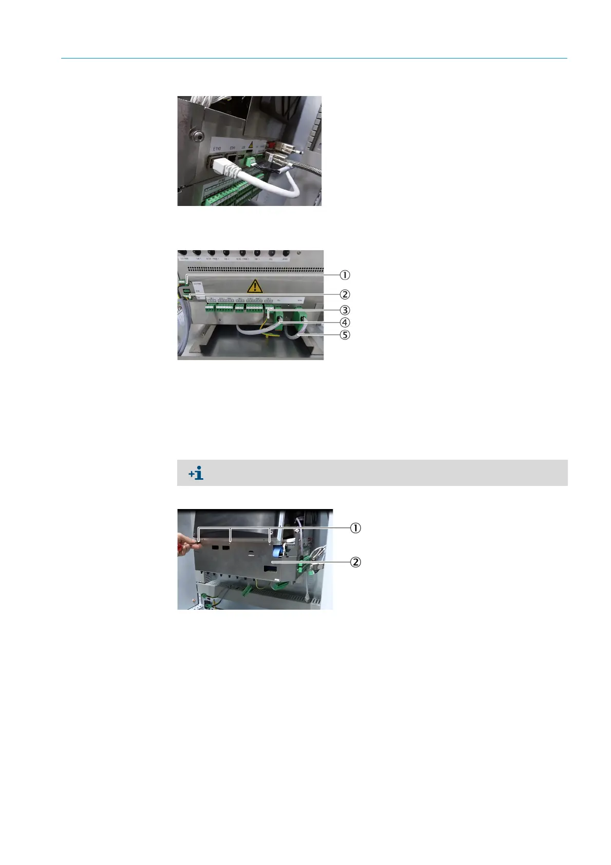
Fig. 207: Electronics unit, plug connections, right, detail
▸ Disconnect plug connections at the bottom.
Fig. 208: Electronics unit, plug connections, bottom
4 Loosen the fastening screws of the electronics unit with a Phillips screwdriver (3 pieces).
Fig. 209: Electronics unit, fastening screws
5 Remove the electronics unit.
6 Perform the work on the electronics unit.
7 Insert the electronics unit into the device cabinet and screw tight (see Fig. 209 “Elec-
tronics unit, fastening screws”, page 131).
8 Attach plug connections and plugs:
▸ Left side (see Fig. 204 “Electronics unit, plug connections, left”, page 130).
1 ELECTRONIC (electronics power supply)
2 FAN (housing fan power supply)
3Grounding
4 CELL (cell)
5 DEVICE (sender/receiver unit)
The plugs are coded and can only be reconnected to the correct socket.
1Fastening screws
2Electronics unit

 Loading...

