84
8024638/AE00/V1-0/2019-09| SICKSERVICE MANUAL | MCS200HW
Subject to change without notice
5 REPAIRS
▸ Loosen the screws of the fastening clip inside with a slotted screwdriver (2 pieces).
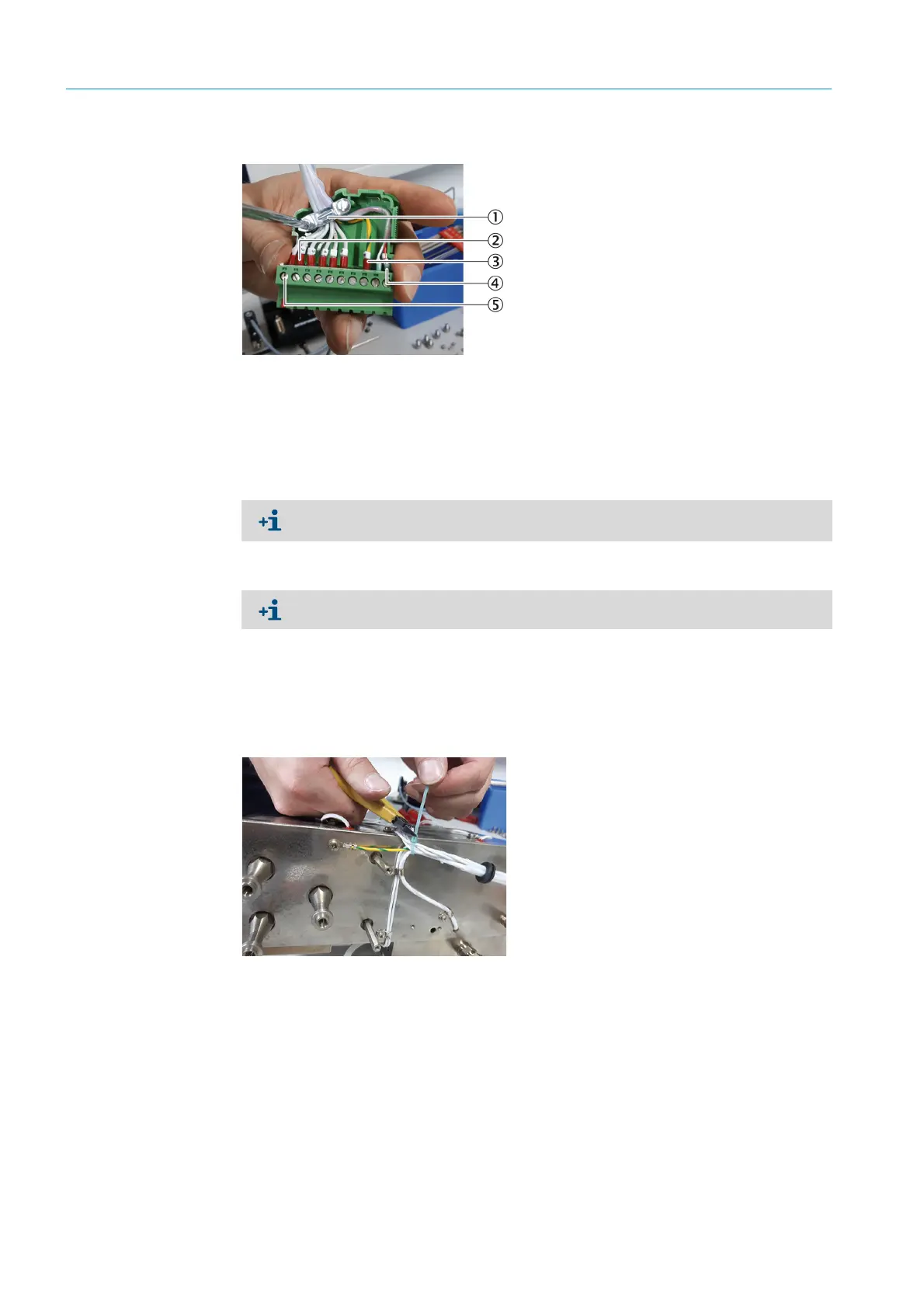
Fig. 120: Contact plug, assignment (example)
6 Loosen the clamping screws of the PT100 cable (see Fig. 122 “Contact plug, assignment
with circuit diagram”, page 85).
7 Pull the PT100 cable out of the cable conduit.
8 Plug in the new PT100.
9 Fasten the cable of the new PT100 with fastening clips.
10 Guide the cable of the new PT100 through the cable conduit to the plug.
11 Bundle all the cables on the back of the cell with cable ties.
Fig. 121: Bundling the cables of the heating cartridges
12 Fasten the cable of the new PT100 with clamping screws in the contact plug (see Fig.
122 “Contact plug, assignment with circuit diagram”, page 85).
▸ Shorten the cables to the appropriate length.
1Fastening clip
2 Leads for thermostatic switches (2) and heating cartridges (4)
3Grounding
4PT100
5Clamping screw
The cable leads are numbered consecutively. Note the assignment of the clamping
screws for reconnection. E.g. with a photo or use the circuit diagram.
The PT100 cable has a red and a white lead.

 Loading...

