94
8024638/AE00/V1-0/2019-09| SICKSERVICE MANUAL | MCS200HW
Subject to change without notice
5 REPAIRS
Fig. 135: Sender/receiver unit, fastening screws, inside, left
6 Close the sender/receiver unit cover.
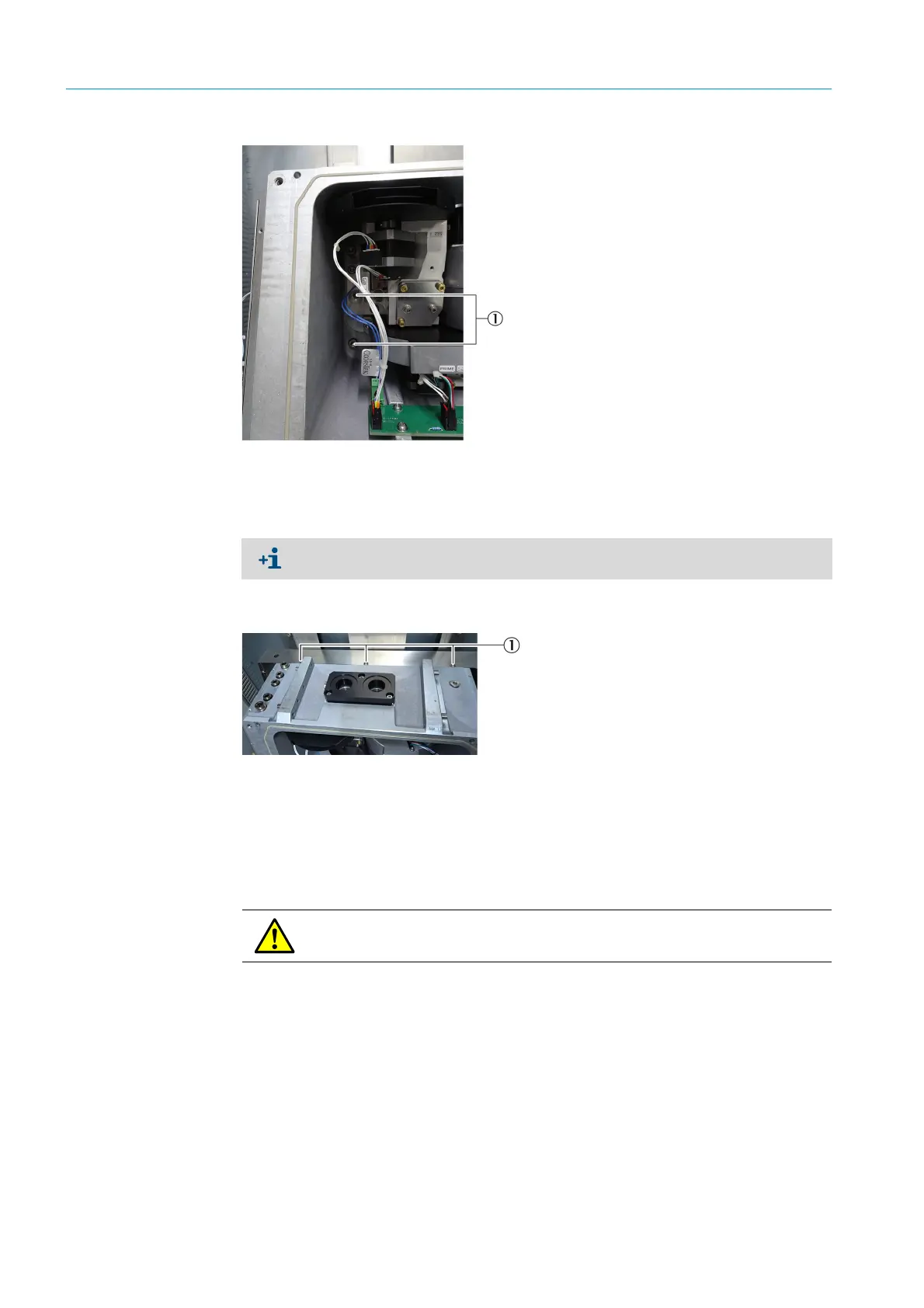
7 Loosen the fastening screws of the sender/receiver unit to the device cabinet using a
Phillips screwdriver (3 pieces).
Fig. 136: Sender/receiver unit, fastening screws
8 Lift the sender/receiver unit with the outer panel out of the device cabinet (see Fig. 138
“Transmit/receive unit, front side”, page 95):
▸ Lay the sender/receiver unit on a level work surface.
▸ Turn the sender/receiver unit with the underside upwards.
9 Loosen the fastening screws of the two templates on the rear side with a 2.5 mm Allen
key (2 pieces).
1Fastening screw
Pay attention to dust protection: Replace the electronics housing cover during work on
the sender/receiver unit.
1Fastening screw
WARNING: Risk of injury through heavy load.
Lift and transport with suitable lifting equipment.

 Loading...

