95
8024638/AE00/V1-0/2019-09| SICK S E R V I C E M A N U A L | MCS200HW
Subject to change without notice
REPAIRS 5
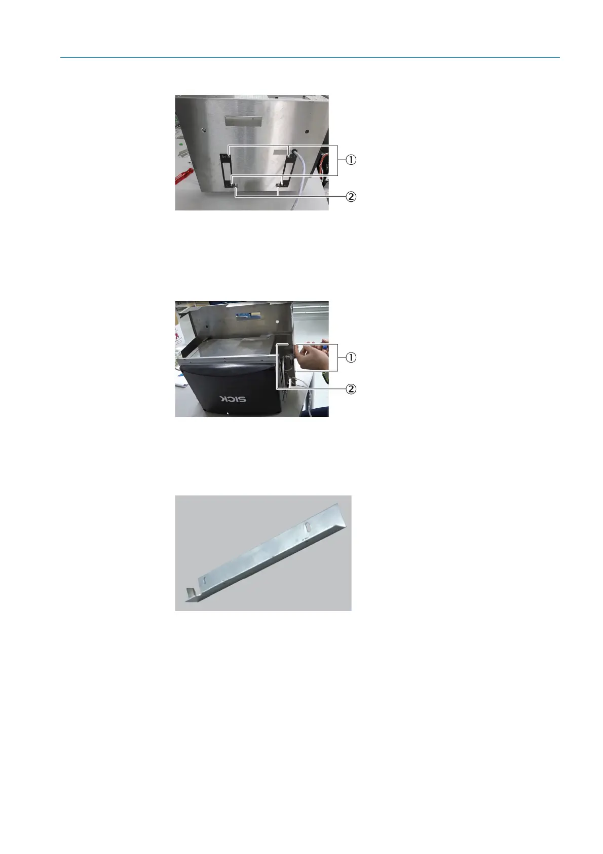
Fig. 137: Sender/receiver unit, rear side
10 Loosen the fastening screws of the inner bracket on the left with a 2.5 mm Allen key.
(2
pieces).
Fig. 138: Transmit/receive unit, front side
11 Remove the inner bracket.
Fig. 139: Sender/receiver unit, inner bracket
12 Disconnect the hose connections of the sender/receiver unit from the outer plate.
13 Remove the complete outer plate:
1 Tilt the outer plate upwards.
2 Pull it off to the back.
3 Pull the power supply cable through the recess.
1 Fastening screw, template
2 Mushroom head mounts
1Fastening screws, outer plate
2 Fastening screws. inner bracket

 Loading...

