PVA-3000 Reference Manual
December 2, 2019 Sifos Technologies
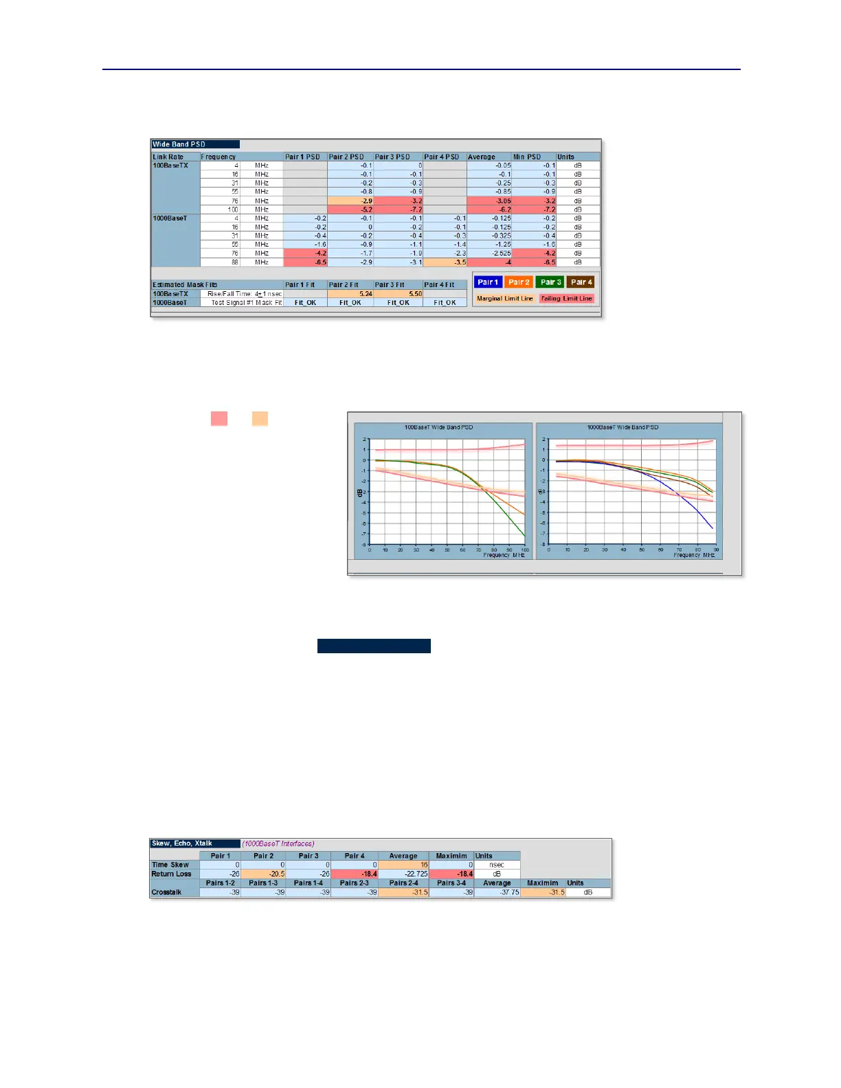
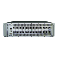
frequency plots are presented also using this tabular data (see Figure 5.9). In these plots, one for 100BaseTx and one
for 1000BaseT, each pair is color coded according to the TIA/EIA convention described earlier in Section 1.3.10.
As described earlier in
Section 1.3.3, Wide
Band PSD provides
fault coverage in areas
such as slew rate and
frequency dependent
power loss problems.
The Estimated Mask
Fits table is produced
using relationships
between PSD at 16
MHz and PSD at upper
frequencies, in other
words, wideband gain-slope information. For 100BaseTx, the Rise/Fall Time is estimated and for 1000BaseT, the
pulse mask fit of Test Signal #1 (Template #1) is estimated. The relationships between wideband PSD parameters and
the Estimated Mask Fit parameters have been refined with formal correlation analysis and will likely evolve further
over a time as more correlations are performed.
Two-tiered (red and tan) test limits
for Wide Band Frequency PSD are
plotted with dotted lines in each PSD
graph (see Figure 5.9) so that limit
excursions are easily observed.
Limits for PSD in the 4 – 16 MHz
region are similar to those in the 1 –
2 MHz band of Low Frequency PSD
since slew rate effects don’t show up
until ~76 MHz and higher. In the
bands between 16 MHz and 76
MHz, some low-side frequency
dependent loss is allowed based on
what pulse masks will tolerate given small amounts of insertion loss inside twisted pair 10/100/1000BaseT ports.
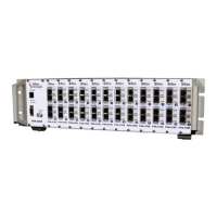
The pva_tx_1000 test produces additional test results displayed both in tabular form (see Figure 5.10) and graphical
form (see Figure 5.11) within the Skew, Echo, and Xtalk section of the standard report. These results are based upon
measurements of the following parameters:
Gigabit Pair Timing Skew (see Sections 1.3.6 and 2.2.2)
Bulk (Wideband) Return Loss (see Sections 1.3.8 and 2.2.2)
Bulk (Wideband) Crosstalk (see Sections 1.3.9 and 2.2.2)
Gigabit pair timing Skew presents timing offset of three gigabit pairs relative to a reference pair, and is therefore a
relative measurement indicting the peak separation in time (or phase difference) of incoming gigabit Ethernet symbols.
While the 802.3 standard allows for up to 50nsec skew, practical levels for an Ethernet port-under-test should be much
smaller since skew will generally be impacted by long cable runs where twisted pairs may not have equivalent
electrical lengths. The standard test report will flag timing skew of 16 nsec or higher.
Bulk, or Wideband
Return Loss is
evaluated against test
limits that were
derived earlier in
Section 1.3.8 and then extended slightly for measurement tolerances. Because 802.3 requirements for return loss of a
port-under-test are both challenging to discern and because they have a frequency dependent component, the limits for
marginal and specification failure indication are only approximate and have been refined using formal correlation
exercises and repeatability studies, and will continue to be refined in the future. Criteria for marginal performance will
typically be in the –20dB range and specification failure will be estimated given readings in the –18 dB range. Figure
5.11 shows the bar graph representation of Bulk Return Loss by pair.
Figure 5.8 Wide Band PSD Tabular Results
Figure 5.9 Wide Band PSD Graphical Representation
Figure 5.10 Skew, Return Loss, and Crosstalk Results in Tabular Form