Description Of Specific Functions
V800 Series High Performance Closed-Loop Vector Inverter User Manual
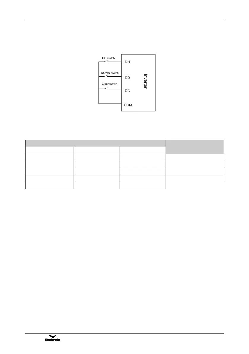
frequency set value of the inverter is shown in Figure 7-2.
Preconditions for below instruction: multifunctional terminal DI1 frequency or process PID setting UP function
([F3.0.00]=15), DI2 sets frequency or process PID DW function ([F3.0.01]=16), and DI5 sets UP/DW with
frequency clear function ([F3.0.04]=17).
Table 7-2 External Switch Status and Current Frequency Set Value of the Inverter
5: Remote UP/DW 2 (go to zero when stopped)
Similar to the case of “4” as above, the inverter will automatically clear current set value after stop.
6: Remote UP/DW 3 (keep value at power-off)
Similar to the case of “4” as above, the set value will be saved automatically after power-off, and the initial set
data will be the set value at the last power-off when the inverter is powered on once again.
7: Remote UP/DW bipolar setting 1 (keep bipolar when stopped)
The basic operation is slimier to that as stated in "the" and the difference is that: in the mode of “4”, the set
frequency is unsigned values (not containing direction information), and the setting range of the frequency is:
0~upper limiting frequency; while in the mode of “7”, the set frequency is signed values (containing direction
changing information), and the setting range of the frequency is: - upper limiting frequency upper limiting
frequency.
The inverter’s actual running direction is according to “XOR” calculation of the command direction (FWD,
REV) and the set frequency direction.
8: Remote UP/DW bipolar setting 2 (keep at power-off)
The basic operation is similar to the case of “7” as above. The set value will be saved automatically after
power-off, and the initial set data will be the set value at the last power-off when the inverter is powered on
once again.
9: Analog input Al1
The frequency set value is given via the analog input AI1; For relevant characteristics please see the
instructions of the parameters F4.0.00 and F4.0.01.
Figure 7-12 Terminal UP/DW wiring sketch
 Loading...