Functional Parameter Table
V800 Series High Performance Closed-Loop Vector Inverter User Manual
Setting Range and Description
Minimum value of
frequency setting
source 2
Maximum value of
frequency setting
source 2
Panel digital set
value of frequency
setting source 2
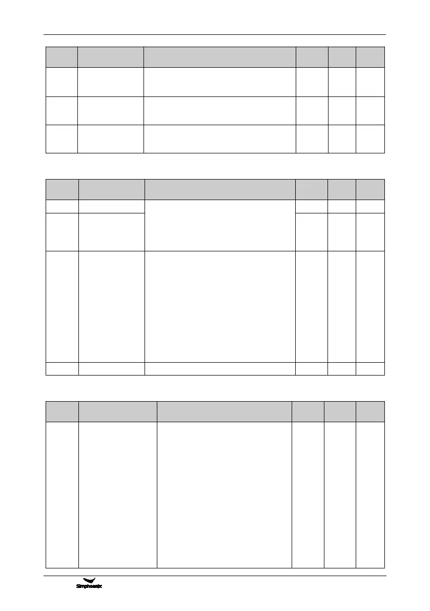
6.2.4 CONTROL COMMAND SOURCE
Setting Range and Description
0: Operating panel
1: External control terminal
2: MODBUS fieldbus /standard expansion card
configuration
3:extension communication moudle
External control
terminal action
mode (H)
_ _ _ X: Control command
0: 2 wire mode 1
1: 2 wire mode 2
2: 3 wire mode 1
3: 3 wire mode 2
_ _ X _: Command power-on first starting
0: Running signal level starting
1: Running signal rising edge starting
(2 wire mode 1 and 2)
_ X _ _: Reserved
X _ _ _: Reserved
6.2.5 START AND STOP
Setting Range and Description
Start/Running
permission(H)
LED _ _ _ X: Start permission
0: Function closed
1: Permitted when the multifunctional
terminal is effective (Function No. 42)
2: Command word from standard fieldbus
(standard expansion card)
LED _ _ X _: Reserved
LED _ X _ _: Running permission
0: Function closed
1: Permitted when the multifunctional
terminal is effective (Function No. 43)
2: Command word from standard fieldbus
(standard expansion card)
LED X _ _ _: The action mode when the
running permission signal is void
0: Free stop