Description Of Specific Functions
V800 Series High Performance Closed-Loop Vector Inverter User Manual
7.13 MULTIFUNCTIONAL INPUT TERMINAL (GROUP F3.0)
F3.0.00~F3.0.05 Multifunctional input
terminals DI1~DI6
F3.0.06 Multifunctional input terminal
DI7/ standard expansion card
F3.0.07 Multifunctional input terminal
DI8/ standard expansion card
F3.0.08 Multifunctional input terminal
DI9/Fin/standard expansion card
Control terminals Dl1~Dl9/Fin are functional programmable switch input terminals; They can define the
Dl1~Dl9/Fin functions respectively by way of the setup of F3.0.00~F3.0.08 values; See their set values and
relevant functions as Table 1 (Contrast Table of Multifunctional Terminals (DI/EDI/SDI) Function).
For example: Define F3.0.00 as 23, so the function of DI1 can be defined as "Simple PLC Multi-stage
Operation Input"; When the DI1 terminal status validates, simple PLC multi-stage operation input function
can be realized.
The function specifications in the table as following:
1~4: Multi-speed control terminals 1~4
By means of the ON/OFF status combinations of these four functional terminals, select the set frequencies
relevant to F6.0.00~F6.0.15 parameters as the current set frequencies of frequency converter. The priority of
the frequency instruction is higher than frequency set channel F0.1.16.
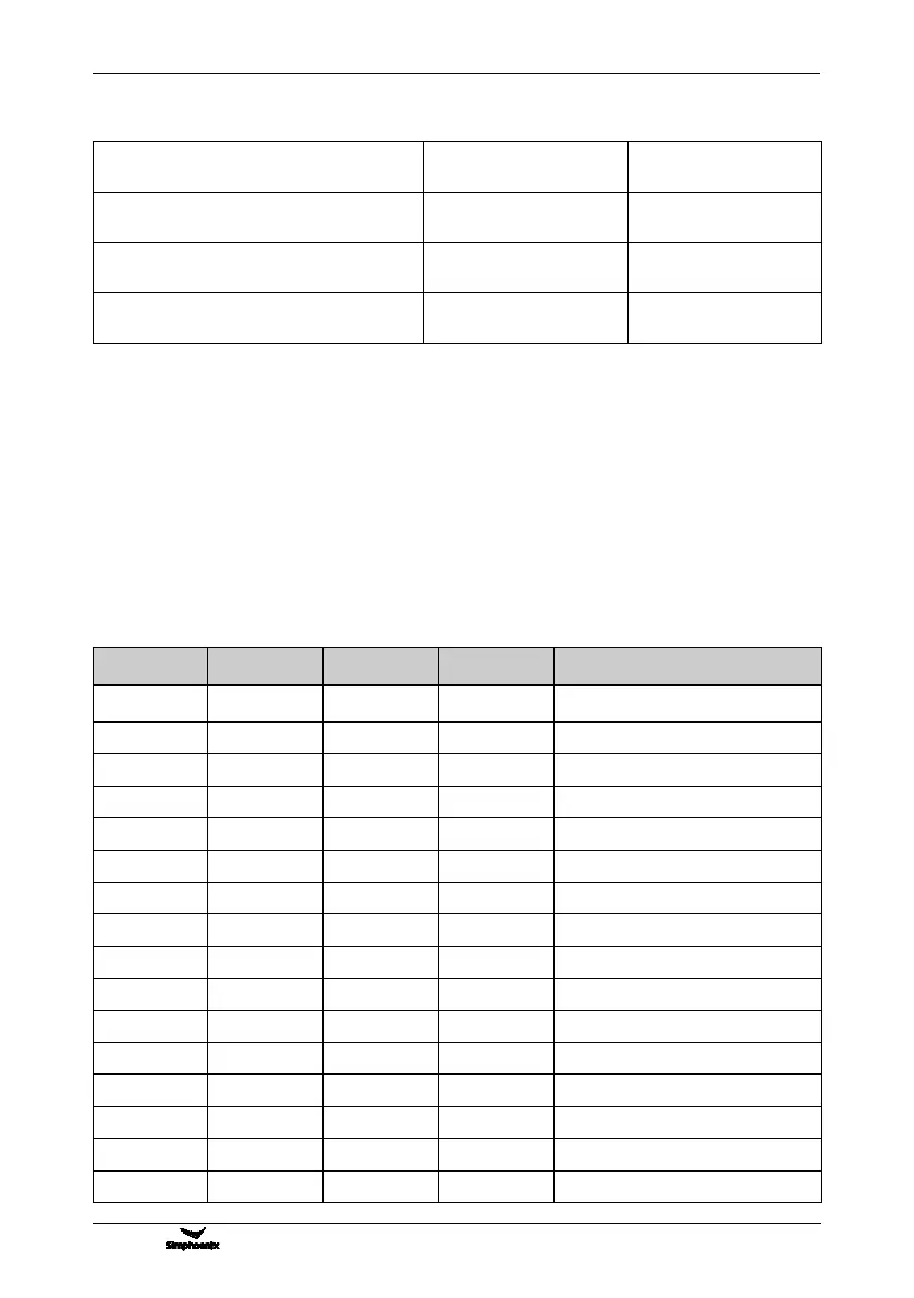
Table 7-3 Multi-speed operation selection table
Ordinary operation frequency
(F0.1.16 determined)
Multi-stage operation frequency 1
Multi-stage operation frequency 2
Multi-stage operation frequency 3
Multi-stage operation frequency 4
Multi-stage operation frequency 5
Multi-stage operation frequency 6
Multi-stage operation frequency 7
Multi-stage operation frequency 8
Multi-stage operation frequency 9
Multi-stage operation frequency 10
Multi-stage operation frequency 11
Multi-stage operation frequency 12
Multi-stage operation frequency 13
Multi-stage operation frequency 14
Multi-stage operation frequency 15