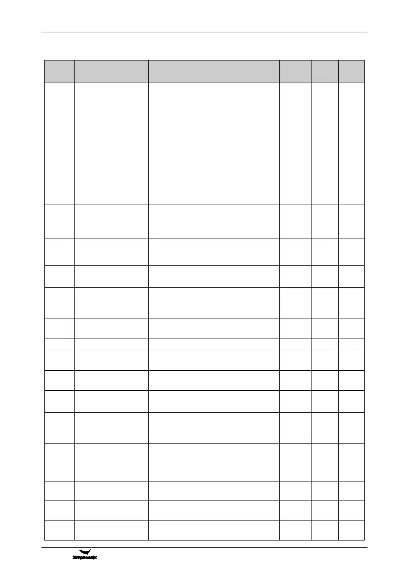
Functional Parameter Table
V800 Series High Performance Closed-Loop Vector Inverter User Manual
6.2.26 AUXILIARY FUNCTIONS
Setting Range and Description
Priority selection of
frequency (revolution)
command source
_ _ _ X: 1
st
priority (highest)
0: No definition
1: Process PID output
2: Compensation PID output
3: Swing frequency running command
4: Automatic multi-stage frequency running
command
5: Multi-stage operating frequency selected
by external terminals
6: Revolution setting channel (F8.0.00)
7: Frequency Setting channel (F0.1.16)
_ _ X _: 2
nd
priority The same as above
_ X _ _: 3
rd
priority The same as above
X _ _ _: 4th priority The same as above
Lower limiting frequency
action mode
0: Output 0 frequency when it is below the
lower limiting frequency
1: Output the lower limiting frequency when it
is below the lower limiting frequency
Automatic voltage
regulation(effective in
V/F mode)
0: Closed 1: Effective
2: Deceleration process void
Automatic energy
-saving operation
0: Void 1: Effective
(effective for asynchronous motors)
0: Void 1: Effective
2: Multifunctional terminal effective
(Function No. 65)
Magnetic flux braking
strength
Use ratio of dynamic
braking
Level of dynamic
braking starting action
Vibration suppression
coefficient
0.0, 0.01~10.00
(only effective in VF control mode)
Load dynamic balance
function
0: Void 1: Effective
2: Multifunctional terminal effective
(Function No. 38)
Reference source for
dynamic balance load
0: Digital setting (F5.3.40)
1: AI1 input 2: AI2 input
3: AI3 input 4: Fieldbus set value 1
5: Compensation PID output
Reference value for
dynamic balance load
Dynamic balance
adjustment gain
Dynamic balance
adjustment limit