V800 Series High Performance Closed-Loop Vector Inverter User manual
10.4 MULTI-PID SETUP, MULTI-PART PID SETUP, FORM A MULTI-
STEP PIDSETUP (TO REDUCE OVERSTRIKE)
10.4.1 PARAMETER SETUP
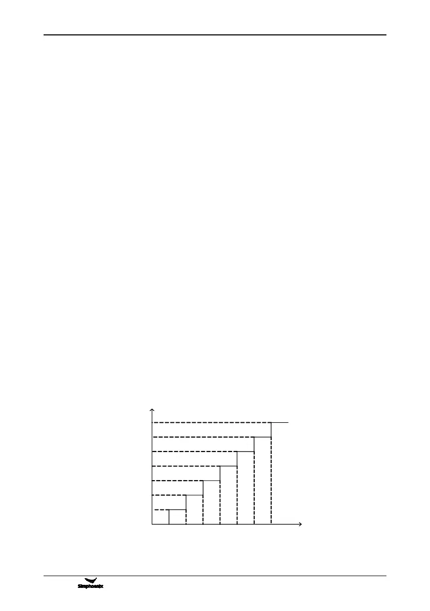
1. F6.1.15= 0053 Multi-part PID operating input (keep the final value stop model)
2. F6.1.31= 1 Time for operating in part 1: 1s
3. F6.1.32= 1 Time for operating in part 2: 1s
4. F6.1.33= 1 Time for operating in part 3: 1s
5. F6.1.34= 1 Time for operating in part 4: 1s
6. F6.1.35= 1 Time for operating in part 5: 1s
7. F6.1.36= 1 Time for operating in part 6: 1s
8. F6.1.37= 5 Time for operating in part 7: 5s
9. F7.0.00= 0001 Process PID input without requirements
10. F7.0.13= 10 100% feedback corresponding simulation: 10V
11. F7.0.17= 15.85 Proportional gain: 15.85
12. F7.0.18= 14 INTEGRAL time: 14
13. F7.1.27= 10 Part 1 in process PID given with 10%
14. F7.1.28= 20 Part 2 in process PID given with 20%
15. F7.1.29= 30 Part 3 in process PID given with 30%
16. F7.1.30= 40 Part 4 in process PID given with 40%
17. F7.1.31= 50 Part 5 in process PID given with 50%
18. F7.1.32= 60 Part 6 in process PID given with 60%
19. F7.1.33= 80 Part 7 in process PID given with 70%
10.4.2 DIAGRAM OF STEP PID VALUE GIVEN