V800 Series High Performance Closed-Loop Vector Inverter User manual
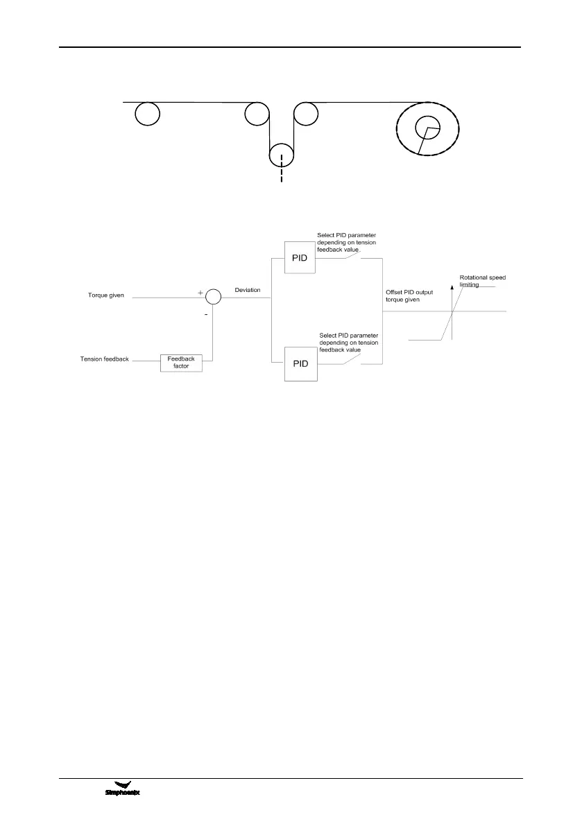
10.2.1 DIAGRAM OF CONSTANT TENSION CONTROL
10.2.2 DIAGRAM OF CONTROL STRUCTURE
10.2.3 CONFIGURATION
1. F0.0.09= 0010 Closed-loop vector controlling mode
2. F8.3.39= 1 Take care, torque model
3. F8.3.40= 8 Torque channel selects offset PID output
4. F8.3.42= 1 Time of torque ascending: 1s
5. F8.3.43= 1 Time of torque descending: 1s
6. F8.3.45= 1500 Positive rotated speed limited set on the basis of motor’s actual rated
rotated speed
7. F8.3.46= 1500 Reverse rotated speed limited set on the basis of motor’s actual rated
rotated speed
8. F8.3.47= 0000 Torque limited channel setup
9. F8.3.48= -100 Smallest torque limited:-K*R*F/T*100% R: biggest semidiameter F: tension
value setting T: torque given T (rated torque of motor output) =9550*P/N,
N: rotated speed given 100 %< K<250%
10. F8.3.50= 100 Biggest torque limited= K*R*F/T*100%
11. F9.0.00= 0101 Input together of offset PID and frequency inverter Independent PID
12. F9.0.01= 100 Offset proportion: R*F/T (rated torque of motor output)*%
13. F9.0.02= 0010 Offset PID outputs bipolar positive deviation
14. F9.0.03= 20 Proportional gain of PID in first part (relatively bigger than parameter value in
second part)
15. F9.0.04= 2 Integral time of PID in first part (relatively smaller than parameter value in
second part)