Installation Of Frequency Inverter
V800 Series High Performance Closed-Loop Vector Inverter User Manual
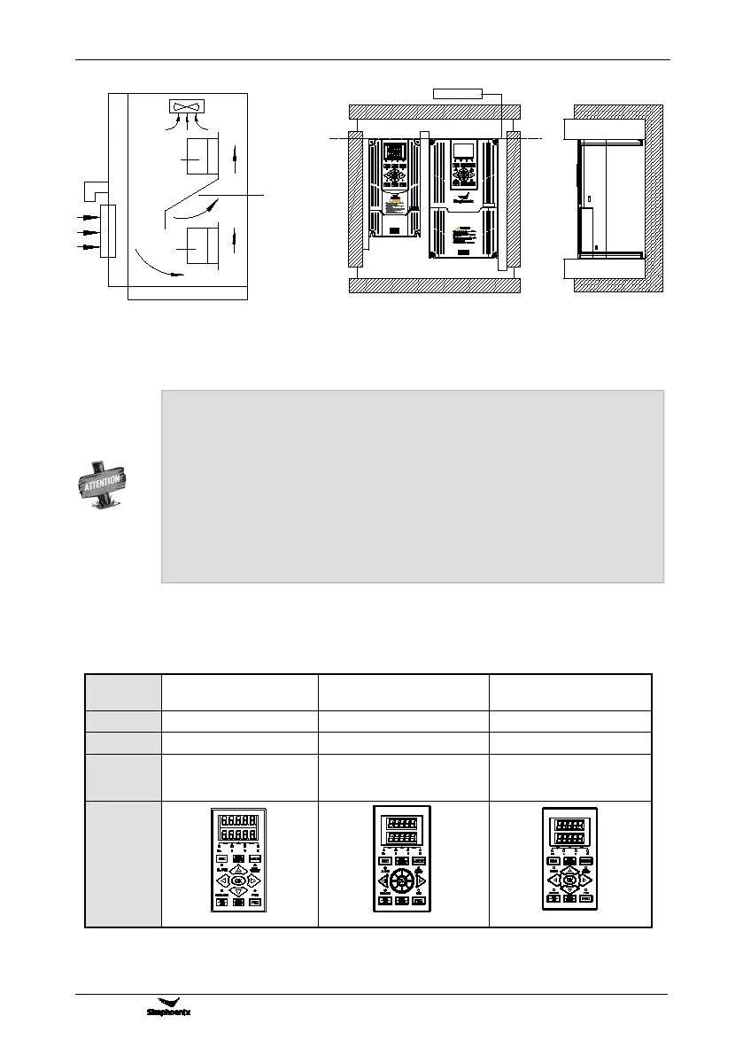
3.2 ASSEMBLY OF OPERATION PANEL
The name of operation panel, model, code and applicable inverter, as follows:
Double line LCD operation
panel(shuttle type)
Double line LCD standard
operation panel
Apply to the inverter below
V800-4T0030G/4T0040P
Apply to
V800-4T0040G/4T0055P ~
V800-4T0300G/4T0370P
Apply to the inverter above
V800-4T0370G/4T0450P
Figure 3-3 Installation sizes of right and
left frequency inverters (4.0KW above)
Baffle plate
Frequency
inverter
Frequency
inverter
Figure 3-2 Installation spacing between
upper and lower frequency inverters
Horizontally close installation is only for 4.0KW below, and -10℃ ~ 45℃ environmental
For parallel installation of frequency inverters with different sizes, please carry out
installation after aligning the upper parts of all the frequency inverters, thus to be in favor
of changing cooling fan.
Please don’t install frequency inverter in the environment with tattered cotton yarn and
damp dust which may cause blockage of cooling fin. If necessary to operate in such
environment, please install in the control cabinet which can keep tattered cotton yarn out.
If necessary to install at the place with more than 1000m height above sea level, please
de-rate operation. See 2.4 product technical indexes and specifications for details.
C
A
A
A
A
B
B
Right-and-left space
upper-and-lower space
Align the upper part
DD
A-50mm above B-30mm above
C-20mm above
D-120mm above