Wiring Of Frequency Inverter
V800 Series High Performance Closed-Loop Vector Inverter User Manual
4.4 WIRING OF MAJOR LOOP TERMINAL
4.4.1 TERMINAL FUNCTIONS
DC side voltage positive terminal
DC reactor can be connected between
P and P+
DC side voltage negative terminal,
Bus voltage input terminal of DC
braking unit can be connected
between P+ and P-.
DC braking resistor can be connected
between P+ and PB
Connect three-phase AC power
supply of grid
Connect three-phase AC motor
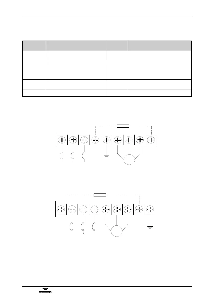
4.4.2 WIRING OF MAJOR LOOP TERMINAL AND TERMINAL BLOCKS
Type I major loop terminal Applicable type: V800-4T0011G/4T0015P ~ V800-4T0030G/4T0040P
R S T P+ E U V W PB
Motor
Three-phase power supply
Ground
Energy consumption braking resistor
Type II major loop terminal Applicable type: V800-4T0040G/4T0055P
R S TP+
E
U V W PB
Motor
Ground
Energy consumption braking resistor
Three-phase power supply