Warning, Alarm Diagnosis And Counter Measures
V800 Series High Performance Closed-Loop Vector Inverter User Manual
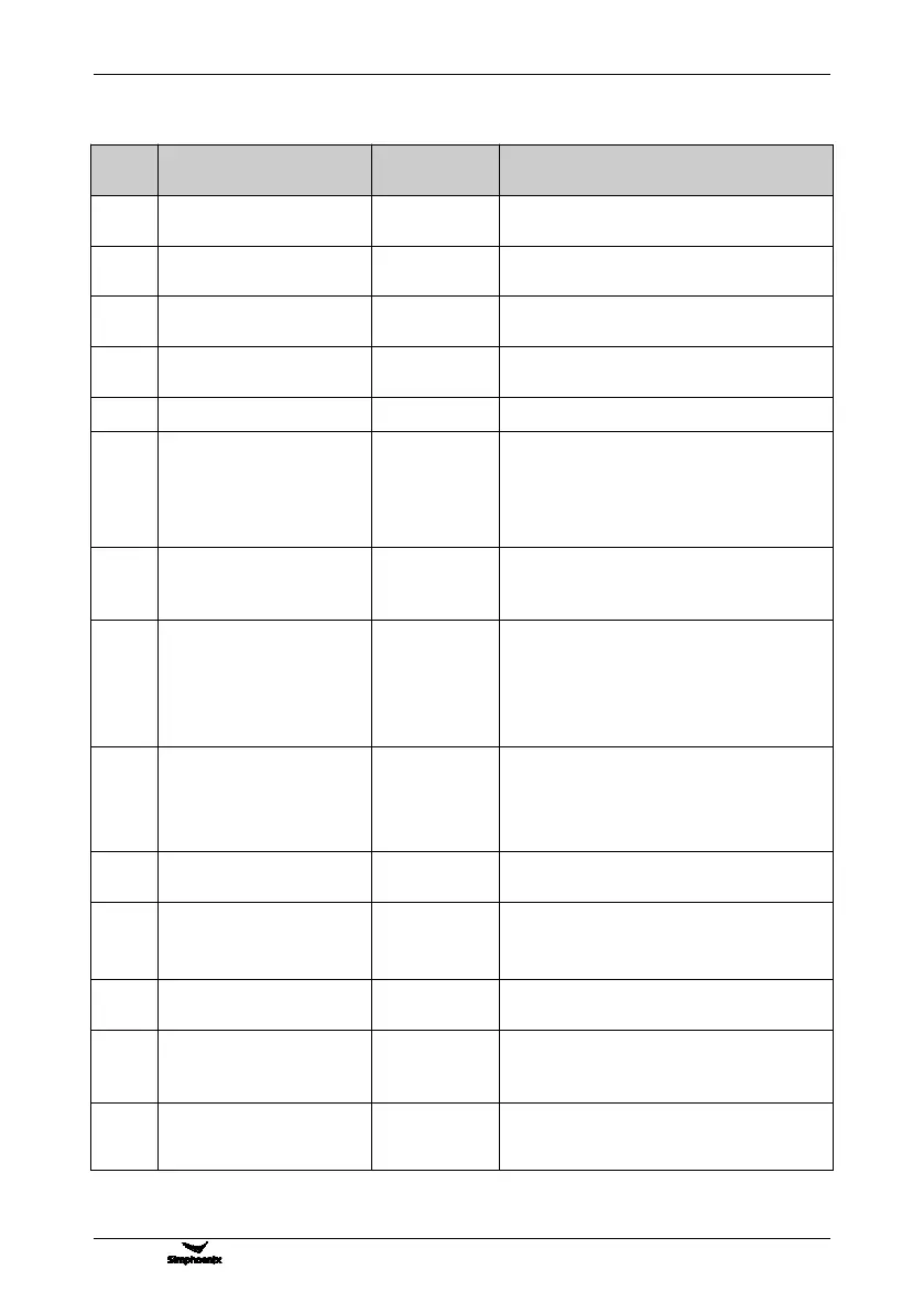
8.1.2 WARNING DISPLAY AND TROUBLESHOOTING
Solutions other than shielding
Over high power supply
voltage
Inspect input power supply
Lower input voltage (under
voltage early warning)
Inspect input power supply
Bad electromagnetic
environment
Improve working environment or seek for
manufacturer’s support
The load is overweight and
protection maybe occurred
Reduce load, or replace a frequency inverter with
larger power
INV overheating early warning
Improve ventilation conditions and reduce carrier
1. Reduce load
2. Prolong acceleration and deceleration time
3. Confirm mechanical system of load
4. Confirm the detection value ([F8.2.34]) and
time ([F8.2.35]) for DEV
1. Adjust frequency setting loop
2. Inspect the setting value of detection value
[F8.2.36]) and time ([F8.2.37]) for OS
The output current of U phase
is deficient/smaller
The output current of V phase
is deficient/smaller
The output current of W phase
is deficient/smaller
Inspect the connecting wire between frequency
inverter and motor or the winding of motor
The starting enabling signal is
deficient
1. Inspect the enabling connection (42) in
multifunctional input terminal and the status of
the terminal (ON/OFF)
2. Inspect whether the starting enabling signal in
bus command word is effective or not
Early warning of unbalanced
three-phase input voltage
Measure the input voltage of all the phases, install
ACR and reduce imbalance rate among phases
AI1 input is disconnected
AI2 input is disconnected
AI3 input is disconnected
1. Inspect the connection of analog input signal
2. Inspect whether there’re signals in the signal
source
Fin input is disconnected
(retained)
The rotating speed detecting
loop is disconnected
1. Inspect the connection of speed measuring
module
2. Seek for manufacturer’s support
No-load operation fails to
identify the parameters of
motor